|
||
| Products Download Events Support Videos | ||

Technical Support
On-Line Manuals
RL-ARM User's Guide (MDK v4)


 Getting Started
To run this RL-CAN STR91x example on a board, ensure you have:
- an MCBSTR9 Evaluation board from Keil
- a ULINK® USB Interface Adapter from Keil
- a USB cable for 5 V power supply.
- Copy the example from \Keil\ARM\Boards\Keil\MCBSTR9\RL\CAN\CAN_Ex1 or from \Keil\ARM\Boards\Keil\MCBSTR9\RL\CAN\CAN_Ex2 to any directory you want to use.
-
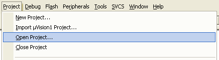
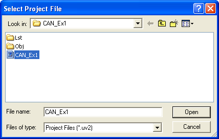
Load the project CAN_Ex1.uv2 or CAN_Ex2.uv2 file from the
copied directory into µVision® 3 IDE (Project — Open
Project...)
-
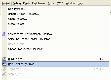
Rebuild the executable file from source files. Click on
Project —; Rebuild all target files on the menu or click on
the toolbar button .
-
Connect the ULINK device to the PC's USB port and to the JTAG
Connector on the MCBSTR9 board.
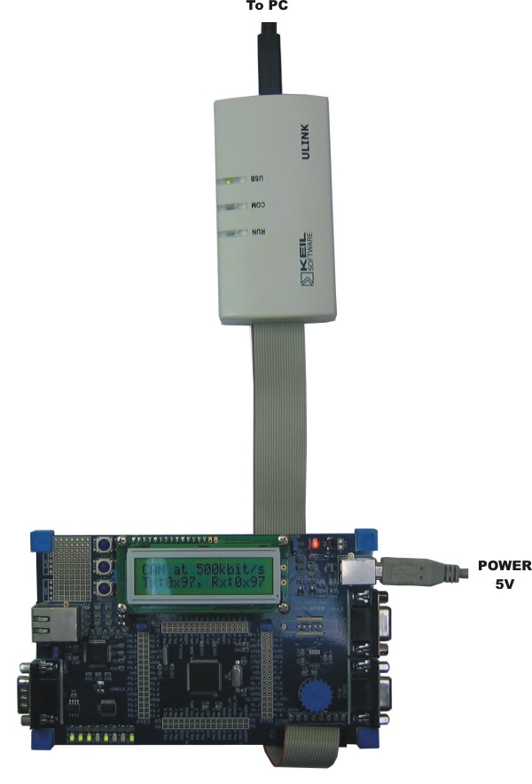
- Power-up the MCBSTR9 board by connecting the board's USB power input to the PC's USB port.
-
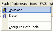
Click on Flash — Download on the menu to download the
executable file to the STR910 flash target on the MCBSTR9
board.
- Rotate the potentiometer and watch the Tx and RX values on the LCD, and the state of the LEDs change according to the position of the potentiometer.
ProductsDevelopment Tools |
Hardware & Collateral |
Downloads |
Support |
Contact |