|
||
| Products Download Events Support Videos | ||

Technical Support
On-Line Manuals
RL-ARM User's Guide (MDK v4)


 Getting Started
To run this RL-CAN AT91SAM7X example on a board, ensure you have:
- an AT91SAM7X-EK Evaluation board from Atmel
- a ULINK® USB Interface Adapter from Keil
- a USB cable for 5 V power supply.
- Copy the example from \Keil\ARM\Boards\Atmel\AT91SAM7X-EK\RL\CAN\CAN_Ex1 or from \Keil\ARM\Boards\Atmel\AT91SAM7X-EK\RL\CAN\CAN_Ex2 to any directory you want to use.
-
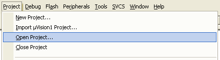
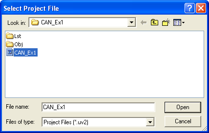
Load the project CAN_Ex1.uv2 or CAN_Ex2.uv2 file from the
copied directory into µVision® 3 IDE (Project — Open
Project...)
-
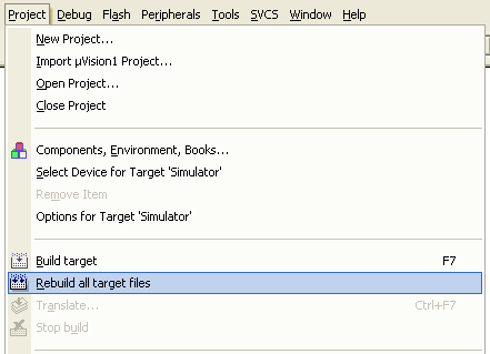
Rebuild the executable file from source files. Click on
Project — Rebuild all target files on the menu or click on
the toolbar button .
-
Connect the ULINK device to the PC's USB port and to the JTAG
Connector on the AT91SAM7X-EK board.
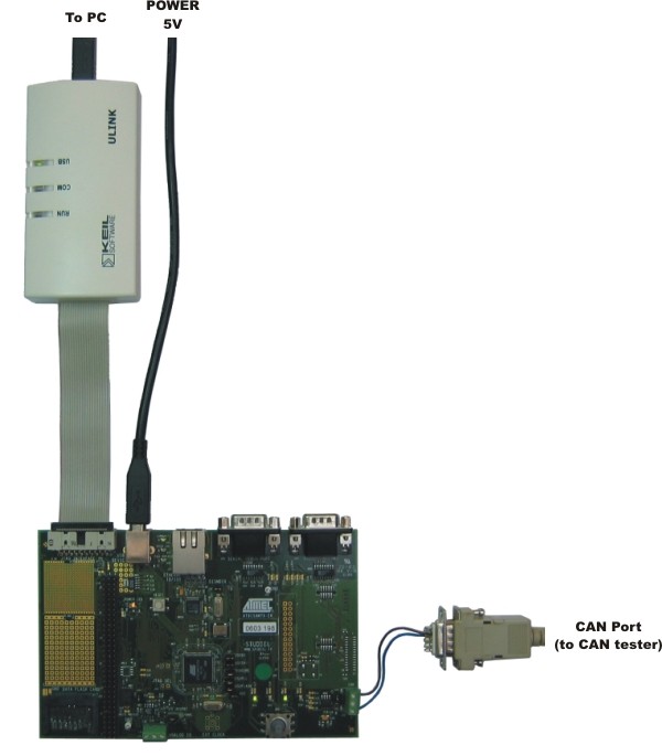
- Power-up the AT91SAM7X board by connecting the board's USB power input to the PC's USB port.
-
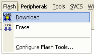
Click on Flash — Download on the menu to download the
executable file to the SAM7X flash target on the AT91SAM7X-EK
board.
- The AT91SAM7X microcontroller has only one CAN port, and it does not have loopback capability. Hence, to demonstrate the functionality of the example, you must connect another CAN device that can send and receive CAN messages from this AT91SAM7X-EK board. After connecting another CAN device, move the joystick on the AT91SAM7X-EK board and see what CAN message has been sent. You can also see the state of the 4 most significant bits of the received message in the 4 LEDs.
ProductsDevelopment Tools |
Hardware & Collateral |
Downloads |
Support |
Contact |