|
||
| Products Download Events Support Videos | ||

Technical Support
On-Line Manuals
RL-ARM User's Guide (MDK v4)
Ethernet Network Interface
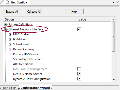
This section describes the options to configure a device for communicating in a LAN. The options are set in the file Net_Config.c directly or using the Configuration Wizard.
Where
-
Ethernet Network Interface enables or disables the
Ethernet Network interface. Disable this option when using the
PPP or SLIP interface to reduce the code size. However, the
Ethernet, PPP, and SLIP network interface can be used
simultaneously. This option corresponds to #define
ETH_ENABLE.
#define ETH_ENABLE 1 // 0=disable; 1=enable
-
MAC Address specifies a six byte Ethernet MAC address. It
must be unique for each Ethernet controller located in the local
area network. The value FF:FF:FF:FF:FF:FF is not
allowed.
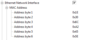
Address byte 1 contains the LSB, which must be 0 for a local MAC address. This option corresponds to #define _MAC1.
Address byte 2 corresponds to #define _MAC2.
Address byte 3 corresponds to #define _MAC3.
Address byte 4 corresponds to #define _MAC4.
Address byte 5 corresponds to #define _MAC5.
Address byte 6 corresponds to #define _MAC6.#define _MAC1 0x1E #define _MAC2 0x30 #define _MAC3 0x6C #define _MAC4 0xA2 #define _MAC5 0x45 #define _MAC6 0x5E
-
IP Address specifies a local IP address, which contains 4
bytes. The value 255.255.255.255 is not allowed.
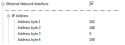
Address byte 1 corresponds to #define _IP1.
Address byte 2 corresponds to #define _IP2.
Address byte 3 corresponds to #define _IP3.
Address byte 4 corresponds to #define _IP4.#define _IP1 192 #define _IP2 168 #define _IP3 0 #define _IP4 100
-
Subnet Mask specifies the Net Mask. This is normally the
class C for small LANs: 255.255.255.0. It is used by
the system to check if the given IP address belongs to an
internal LAN or an external WAN.
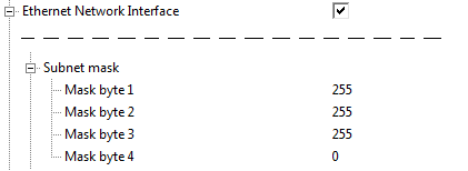
Mask byte 1 corresponds to #define _MSK1.
Mask byte 2 corresponds to #define _MSK2.
Mask byte 3 corresponds to #define _MSK3.
Mask byte 4 corresponds to #define _MSK4.#define _MSK1 255 #define _MSK2 255 #define _MSK3 255 #define _MSK4 0
-
Default Gateway specifies the IP address of the default
gateway. It is used when accessing the external WAN. If the
application is used on a local LAN only, then these values are
irrelevant.
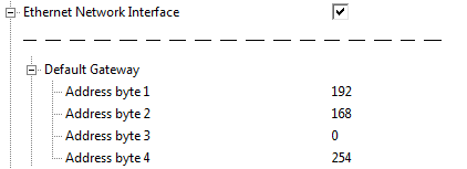
Address byte 1 corresponds to #define _GW1.
Address byte 2 corresponds to #define _GW2.
Address byte 3 corresponds to #define _GW3.
Address byte 4 corresponds to #define _GW4.#define _GW1 192 #define _GW2 168 #define _GW3 0 #define _GW4 254
-
Primary DNS Server specifies the IP address of the primary
DNS Server. The DNS Client sends IP address resolution requests
to this address. The settings are irrelevant when the DNS Client
is disabled.
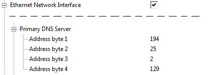
Address byte 1 corresponds to #define _pDNS1.
Address byte 2 corresponds to #define _pDNS2.
Address byte 3 corresponds to #define _pDNS3.
Address byte 4 corresponds to #define _pDNS4.#define _pDNS1 194 #define _pDNS2 25 #define _pDNS3 2 #define _pDNS4 129
-
Secondary DNS Server specifies the IP address of the
secondary DNS Server. This DNS Server is used when the primary
DNS Server is down or not accessible. In this case, the DNS
Client automatically switches to a backup secondary DNS Server if
a non-zero address is provided.
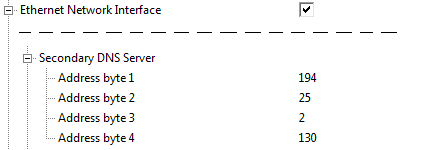
Address byte 1 corresponds to #define _sDNS1.
Address byte 2 corresponds to #define _sDNS2.
Address byte 3 corresponds to #define _sDNS3.
Address byte 4 corresponds to #define _sDNS4.#define _sDNS1 194 #define _sDNS2 25 #define _sDNS3 2 #define _sDNS4 130
-
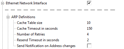
ARP Definitions caches the addresses of remote peers (ARP - Ethernet Address Resolution Protocol). The following ARP parameters can be configured:
-
Cache Table size specifies the size of ARP cache
table. It defines how many cache entries can be kept in the
ARP cache. Increase this value when using multiple
simultaneous IP connections. This option corresponds to
#define ARP_TABSIZE.
#define ARP_TABSIZE 10
-
Cache Timeout in seconds specifies the timeout for an
ARP cache entry. After a timeout, the Permanent IPs are
refreshed, and the Temporary IPs are removed from the cache.
The Timeout (Keep-alive) Timer is reset on every access to
the cache entry. This option corresponds to #define
ARP_TIMEOUT.
#define ARP_TIMEOUT 150
-
Number of Retries is the maximum number of retries to
resolve the Ethernet MAC address of the remote peer. This
option corresponds to #define ARP_MAXRETRY.
#define ARP_MAXRETRY 4
-
Resend Timeout in seconds specifies the waiting
interval between two re-sends. When this timeout has expired
and no response has been received from the remote peer, the
ARP request is resent. This option corresponds to
#define ARP_RESEND.
#define ARP_RESEND 2
-
Send Notification on Address changes enables or
disables the Gratuitous ARP Service. When it is enabled, the
embedded host will broadcast a Gratuitous ARM notification at
startup, or when the local IP address has changed. This
option corresponds to #define ARP_NOTIFY.
#define ARP_NOTIFY 0 // 0=disable; 1=enable
-
Cache Table size specifies the size of ARP cache
table. It defines how many cache entries can be kept in the
ARP cache. Increase this value when using multiple
simultaneous IP connections. This option corresponds to
#define ARP_TABSIZE.
-
IGMP Group Management enables or disables sending or receiving IP Multicast packets (IGMP - Internet Group Management Protocol). In order to receive Multicast packets, a host must first join a Host Group with specified Host Group IP address.
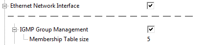
This option corresponds to #define IGMP_ENABLE.
#define IGMP_ENABLE 1 // 0=disable; 1=enable
-
Membership Table size specifies the size of IGMP Host
Group table. It defines how many Host Groups a host can join.
This option corresponds to #define IGMP_TABSIZE.
#define IGMP_TABSIZE 5 // join max. 5 host groups
-
Membership Table size specifies the size of IGMP Host
Group table. It defines how many Host Groups a host can join.
This option corresponds to #define IGMP_TABSIZE.
-
NetBIOS Name Service enables or disables the NBNS Name
Service. When NBNS is enabled, the device can be accessed by its
name in a LAN. For example, use the command: PING
mcb1700 instead of PING 192.168.0.100.
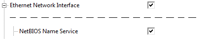
This option corresponds to #define NBNS_ENABLE.
#define NBNS_ENABLE 1 // 0=disable; 1=enable
-
Dynamic Host Configuration enables or disables the DHCP
Service. When DHCP is enabled, the device obtains all network
parameters like IP address, net mask, default gateway, primary
and secondary DNS servers automatically from the DHCP server on
the LAN. Enable also the option NetBIOS Name Service to
access the hardware by name.
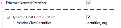
This option corresponds to #define DHCP_ENABLE.
#define DHCP_ENABLE 1 // 0=disable; 1=enable
-
Vendor Class Identifier specifies a string, which is
added to the DHCP request message. The Vendor Class
Identifier can be used to selectively identify a device on a
DHCP server. For example, the DHCP server can assign an IP
address to a specific Vendor Class group and ignore all other
DHCP clients with a different VCI. This option corresponds to
#define DHCP_VCID.
#define DHCP_VCID "identifier_strg" // default is an empty string ("") -
Bootfile Name enables or disables the DHCP option 67.
If this option is enabled, a DHCP client requests also a
Bootfile Name parameter from a DHCP server. When enabled, the
user needs to provide also a http_cbfunc() notification
function. This function gets called by DHCP client, if option
67 is received in DHCP response to notify the user.
#define DHCP_BOOTF 0 // 0=disable; 1=enable
-
Vendor Class Identifier specifies a string, which is
added to the DHCP request message. The Vendor Class
Identifier can be used to selectively identify a device on a
DHCP server. For example, the DHCP server can assign an IP
address to a specific Vendor Class group and ignore all other
DHCP clients with a different VCI. This option corresponds to
#define DHCP_VCID.
ProductsDevelopment Tools |
Hardware & Collateral |
Downloads |
Support |
Contact |