|
||
| Products Download Events Support Videos | ||

Technical Support
On-Line Manuals
RL-ARM User's Guide (MDK v4)


 Memory Card Drive
Memory Card Drive options allow configuring RL-FlashFS to use memory cards. Set the options manually or use the Configuration Wizard.
The RL-FlashFS supports two Memory Card drives. The options are identical for both drives and can operate at the same time.
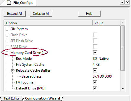
The following options can be set:
-
Memory Card Drive 0 enables support for SD/MMC Flash
memory card device.
#define MC0_EN 1 // 0=disable; 1=enable
-
Bus Mode specifies the access mode for SD/MMC Flash memory
card device. This option should be set to 0 for SD-Native
mode or to 1 for SPI mode.
RL-FlashFS can use SPI mode or SD/MMC native mode to initialize and control the memory card drive.
- SPI mode - the required routines are in the low level SPI driver. It handles data transfer on the SPI interface. In SPI mode the memory card control is handled in software.
- Native mode - can be used if a device has integrated a Multimedia Card Interface peripheral. The required routines are in the low level MCI driver module. Native mode is faster then SPI mode because the memory card control is handled in hardware.
The SPI driver or Native mode driver is not included in the RL-FlashFS library because it is device dependent. Hence, copy the driver to the project folder and include it into the project.
#define MC0_SPI 0 // 0=SD-Native; 1=SPI
-
File System Cache defines the data caching and specifies
the Cache Buffer size. When SD/MMC Memory Card is
controlled in SD-Native mode, data caching might increase
the file r/w speed. When caching is enabled, Multiple Sector Read
and Multiple Sector Write commands are used to control the SD/MMC
memory card data read and write. Turn off the data cache if the
application is low on memory and the file read/write speed is not
important. The cache buffer size is specified in KBytes.
#define MC0_CASZ 4
-
Relocate Cache Buffer allows to allocate the RAM buffer at
a specific address in the memory space. When disabled, the linker
assigns the address of the RAM buffer.
#define MC0_RELOC 1 // 0=disable; 1=enable
-
Base address specifies the location address of the Cache
Buffer. This option is active when Relocate Cache Buffer
is enabled.
#define MC0_CADR 0x7FD00000
-
FAT Journal protects the file system from a potential
damage during power failure and keeps the system in a consistent
state. This option does not protect files that are written during
power failure.
#define MC0_FSJ 1 // 0=disable; 1=enable
-
Default Drive [M0:] enables the Memory Card Drive 0 as a
default system drive. This drive is used, when no drive letter is
specified in a file name. The drive label M is considered
as M0.
#define MC0_DEF 1 // 0=disable; 1=enable
 Related Knowledgebase Articles
ProductsDevelopment Tools |
Hardware & Collateral |
Downloads |
Support |
Contact |