|
||
| Products Download Events Support Videos | ||

Technical Support
On-Line Manuals
µVision3 User's Guide
Setup
To setup the Logic Analyzer use the menu command Debug — Logic Analyzer. You may enter the LA command in the command window to setup signals or remove all signals from recording (see also Logic Analyzer — Setup in Detail).
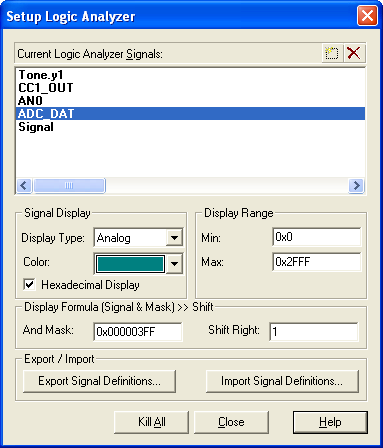
The Setup... dialog defines variables for signal recording and configures the display output:
Current Logic Analyzer Signals lists the current configuration.
- Add a variable or VTREG for signal recording with New (Insert key). Delete (Delete key) removes a selected signal.
- Select a signal name in this list to modify the following settings.
Signal Display configures the appearance of a selected signal.
- Display Type sets the graphical display output to: Analog, Bit (0 or 1), or State (signal transitions).
- Color sets signal display color.
- When Hexadecimal Display is enabled signal values are shown as HEX values. When disabled decimal values are shown.
Display Range configures the value range of a selected signal.
- Min Value and Max Value selects the display range for Analog display type. You may use decimal or HEX values for the range selection.
Display Formula (Signal & Mask) >> Shift extracts specific bits from a signal value for displaying.
- And Mask specifies a AND mask for the value display of a signal.
- Shift Right specifies a shift right factor for the value display of a signal.
Export / Import allows you to store and restore the current Logic Analyzer Setup.
- Export Signal Definitions creates a file with the current setup of the signal definitions.
- Import Signal Definitions restores a signal definition setup from a file.
ProductsDevelopment Tools |
Hardware & Collateral |
Downloads |
Support |
Contact |