|
||
| Products Download Events Support Videos | ||

Technical Support
On-Line Manuals
µVision User's Guide


 Interrupt Signal
The following signal function generates GPIO interrupt signals on 2 pins.
/*----------------------------------------------------------------------
  Generates a number of pulses on GPIO 0.14 and GPIO 1.24
----------------------------------------------------------------------*/
SIGNAL void GPIO_0_14_Square (unsigned int pulses)  {

  printf ("%d Square Pulses on GPIO 0.14\n", pulses);

  PORT0 = 0x0;
  PORT1 = 0x0;
  while (pulses--)
  {
    PORT0 |=   (1 << 14);          // set    pin 0.14
    swatch (0.02);
    PORT1 &=  ~(1 << 24);          // reset  pin 1.24
    swatch (0.01);
    PORT1 |=   (1 << 24);          // set    pin 1.24
    PORT0 &=  ~(1 << 14);          // reset  pin 0.14
    swatch (0.02);
  }
}


GPIO_0_14_Square (100);            // 100 Pulses at debugger startup

DEFINE BUTTON "EINT1 10  Pulses", "GPIO_0_14_Square (10)"
DEFINE BUTTON "EINT1 100 Pulses", "GPIO_0_14_Square (100)"
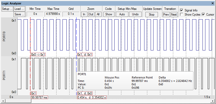
Start debugging in simulation mode and drag the port into the Logic Analyzer. Open the Toolbox and click the buttons EINT1 10 Pulses or EINT1 100 Pulses to view the signal output on the pins of PORT0.14 and PORT1.24:
ProductsDevelopment Tools |
Hardware & Collateral |
Downloads |
Support |
Contact |