|
||
| Products Download Events Support Videos | ||

Technical Support
On-Line Manuals
µVision User's Guide
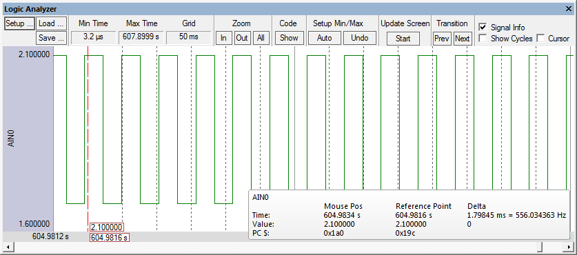
Square Wave Signal
The following signal function generates a square wave signal. The input signal is provided to the VTREG ADC0. The variables volts, frequency, offset, and duration are used to adjust the signal.
/*-----------------------------------------------------
  Generates an Square Wave Signal on AD Channel 0
-----------------------------------------------------*/
SIGNAL void AIN0_Square (void)  {
  float volts;        // peak-to-peak volatage
  float frequency;    // output frequency in Hz
  float offset;       // volatge offset
  float duration;     // duration in Seconds

  volts     = 0.5;
  offset    = 1.6;
  frequency = 2400;
  duration  = 0.5;

  printf ("Square Wave Signal on AD Channel 0.\n");

  while (duration > 0.0)  {
    AIN0 = volts + offset;
    swatch (0.5 / frequency);
    AIN0 = offset;
    swatch (0.5 / frequency);
    duration -= 1.0 / frequency;
  }
}

DEFINE BUTTON "AIN0 Sqr","AIN0_Square()"
Start debugging in simulation mode and drag the port into the Logic Analyzer. Open the Toolbox and click the button AIN0 Sqr to view the signal output:
ProductsDevelopment Tools |
Hardware & Collateral |
Downloads |
Support |
Contact |