USB Component  Version 6.6
MDK-Professional Middleware for USB Device and Host
 All Data Structures Functions Variables Enumerations Enumerator Groups Pages
USB Device

This chapter describes the software structure of the USB Device Component and its use for creating applications. The USB Device Component simplifies the software development of microcontroller systems that interface to a USB Host.

Attributes of the USB Device Component:

  • Supports Low-Speed, Full-Speed and High-Speed.
  • Supports standard USB Classes with multiple device class instances.
  • Supports composite devices. Combine USB Device Classes to create a composite device.
  • Supports multiple USB Devices on a single microcontroller with more than one USB Device controller.
  • Provides User Code Templates for implementing the USB Device functionality.
  • Provides an user-friendly configuration file for each device class to generate USB Descriptors.
  • Flexibly assigns USB Endpoints to the microcontroller USB Device peripheral.
  • Provides USB Device Examples to show the use of the software stack.

For interfacing to an USB Host Computer, additional software may be required. Page Interface to an USB Host Computer shows an example for such a software running on Windows PCs.

RTE Components

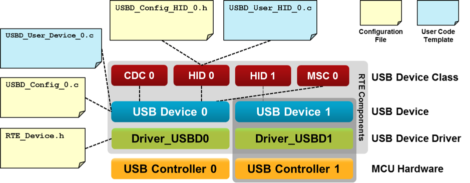
The picture shows the relationship between RTE Components and the microcontroller's USB Device peripheral (USB Controller). RTE Components provide configuration files and user code templates. Configuration files configure the RTE Components, hardware interfaces, memory resources and USB Device driver parameters. They can have an impact on multiple RTE Components (for example RTE_Device.h configures the USB Controller 0 and Driver_USBD0). User code templates provide the skeleton for implementing the USB Device functionality.

The grey area around the RTE Components USB Device 1 and Driver_USBD1, as well as USB Controller 1 means that these components are optional and can only be used if a microcontroller device has multiple USB controllers present. If this is the case, an USB Device Class can be connected to any of the USB Device Instances.

usb_device_blocks_config_files.png
USB Device Structure

USB Device peripherals can have one or more of the following USB Device Classes:

  • Audio Device Class (ADC) is used to exchange streaming audio data between the USB Host and the USB Device.
  • Communication Device Class (CDC) provides virtual communication port functionality to the USB Host.
  • Human Interface Device (HID) is typically used to implement a keyboard, joystick, or mouse. The HID Class can be also used for low bandwidth data exchange.
  • Mass Storage Class (MSC) is used to connect various storage devices to an USB Host. Mass Storage Class media can be an SD card, internal or external Flash memory, or RAM.
  • Custom Class is used to implement either a standard or a vendor specific USB Device Class.

Generic information about USB Device Classes can be found on the USB-IF's Approved Class Specification Documents page.

Multiple RTE Component instances can interface with more than one USB Controller or can implement multiple USB Device Classes. RTE Component instances are numbered. The number is appended to the RTE Component name, related configuration files, and user code templates. Each RTE Component has a separate configuration file. For example, for HID 0 and HID 1 the configuration files have the name USB_Config_HID_0.h and USB_Config_HID_1.h.

Note
The default configuration settings are pre-configured for one instance of an USB Device or USB Device Class in a non-composite device peripheral. For other combinations the settings need to be edited to ensure proper operation. The USB Composite Device example shows how to implement and configure a composite devices

Create an USB Device Application

The steps to create a microcontroller application that uses USB communication with an USB Device controller are:

  1. Select RTE Components along with the USB Device Classes that are required for your application.
  2. Enable and configure the USB Device Driver.
  3. Configure the USB Device that connects the USB Middleware to the microcontroller USB peripheral.
  4. Configure USB Device Class Configuration and USB Endpoint Settings for each selected USB Device Class and instance.
  5. Configure the System Resources according to the USB Device component's Resource Requirements.
  6. Implement the Application Code using code templates that are provided for the USB Device Classes.

For interfacing to an USB Host computer, standard USB Device Classes drivers can be used. This may require additional software development for the USB Host application. An exemplary application for interfacing to an USB HID Device is explained here.

RTE Component Selection

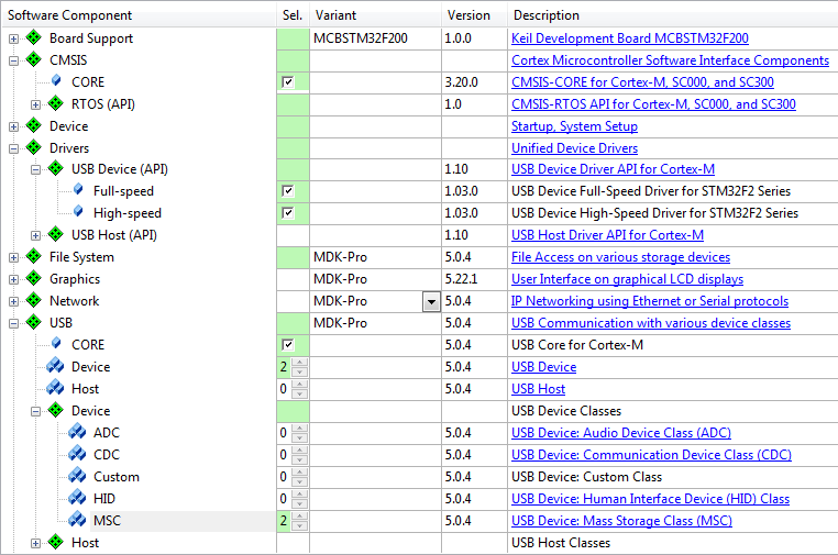
Only a few steps are necessary to complete the RTE Component selection:

  1. From the USB Component:
    • Select USB:CORE that provides the basic functionality required for USB communication.
    • Set USB:Device to '1'. This creates one USB Device for communication with the USB Host.
    • Select the desired USB Classes (HID, MSC, CDC, ADC, or Custom Class). For example, set USB:Device:HID to '1' to create a single HID Class Device. If you select more than one class or multiple instances of the same class on the same device, you will create a Composite USB Device.
  2. From the Drivers Component:
    • Select an appropriate USB Device driver suitable for your application.
  3. From the Device Component:
    • Additional device specific drivers may be required according to the validation output.
  4. From the CMSIS Component:
    • Select the CMSIS:CORE to provide the core interface to the processor.
    • Select a suitable CMSIS:RTOS that is a required for the USB Component.
rteusbx.png
RTE Component Selection
Note
  • Most microcontrollers have only one USB Controller implemented in hardware and only one driver Driver_USBD0 is available. In this case, only one USB:Device can be selected to generate USB Device 0.
  • On a single USB Device 0 an USB Composite Device may be implemented that combines multiple USB Device Classes.
  • When a microcontroller implements multiple USB Controllers an additional USB Device 1 can be generated by setting USB:Device to '2'.

USB Driver and Controller

The USB Device Driver and the USB Controller of the microcontroller need to be correctly configured. In particular this means:

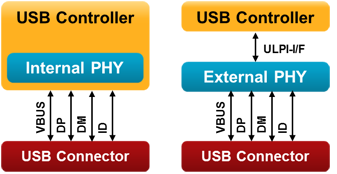
  • The USB Device Driver selected under the Drivers Component is typically configured with the RTE_Device.h configuration file. While this file provides multiple options, it is typically sufficient to enable the USB Device peripheral related to this driver. Some microcontrollers may require settings that are related to a physical layer interface (PHY). The picture below shows two possible variants. Either, the USB PHY is integrated into the controller, or an external chip is used for providing the USB signal lines:

    usb_phy.png
    USB Controller and PHY Setups
  • The USB Controller of the microcontroller typically needs specific clock settings. Consult the user's guide of the microcontroller to understand the requirements. Alternatively, you may copy the setup of an USB Device example (in case your hardware setup is similar to that of the chosen evaluation boards).

USB Device Configuration

The configuration file USBD_Config_n.c is listed in the Project Windows under the Component USB and contains a number of important settings for the specific USB Device.

  • The Driver_USBD# number is set according to the selected USB Controller. This specifies which driver will be used for the USB Device determining the pin-out as well. For single USB Device Controllers it will be '0'.
  • High-Speed may be selected if supported by the USB Controller.
  • The Vendor ID (VID) needs to be set to a private VID. The default Vendor ID is owned by Keil and must not be used for actual products. Please visit USB-IF for more information on how to apply for a valid Vendor ID.
  • Every device variant needs an unique Product ID. Together with the VID, it is used by the Host computer's operating system to find a driver for your device.
  • The Device Release Number will be shown in Windows and Linux systems as “Firmware Revision”. The number will be interpreted as “binary coded decimal”, meaning that 0x0101 will be shown as firmware revision 1.01.
  • The Manufacturer and the Product String can be set to identify the USB Device on the USB Host.

Refer to USB Core Configuration for more configuration options of the USB Device.

Note
You can configure the USB Device at run-time using the functions from the USB Device Core API. The section USB Device Core explains the details. Implement the run-time specific behavior with the user code template USBD_User_Device_n.c.

USB Device Class Configuration and USB Endpoint Settings

The USB Device Class Parameters and Endpoint Settings are configured in separate files for each USB Device Class and separately for each instance. The configuration files contain Device Class specific Endpoint Settings Numbers and are listed in the Project Window under the Component USB.

  • USBD_Config_ADC_n.h configuration for Audio Device Class (ADC).
  • USBD_Config_CDC_n.h configuration for Communication Device Class (CDC).
  • USBD_Config_HID_n.h configuration for Human Interface Device Class (HID).
  • USBD_Config_MSC_n.h configuration for Mass Storage Device Class (MSC).
  • USBD_Config_CustomClass_n.h configuration for Custom Class.

Each USB Endpoint can only be used once on the same USB Device. It has to be made sure that the different USB Device Classes or multiple instances of the same USB Device Class use different Endpoints. The default configuration supports applications that use a single USB Device Class. The remaining parameters are specific settings that configure parameters for USB communication speed and the USB Device Class.

System Resource Configuration

For proper operation, the USB Device Component requires some system configuration settings. The requirements are:

  • Additional stack size of 512 bytes. This can be configured in the device's startup_device.s file (Stack_Size).
  • The USB Device component uses CMSIS-RTOS threads. Depending on the number of supported USB Device Classes, you need to configure additional settings in the RTX_Conf_CM.c file.

For more information, check the USB Device component's Resource Requirements section.

User Code Implementation

User code template files provide function templates used to implement USB Device Class functionality. The available functions are explained in the Reference section of the USB Component. These routines can be adapted to the needs of the microcontroller application, in case different then default functionality is needed.

The following templates are available for the USB Device component:

Template Name Purpose
USBD_User_ADC_n.c Required functions to create an ADC device.
USBD_User_ADC_Headphone_n.c Implements functions to create an ADC device containing speakers and a microphone.
USBD_User_CDC_ACM_n.c Required functions to create a CDC (ACM) device.
USBD_User_CDC_NCM_n.c Required functions to create a CDC (NCM) device.
USBD_User_CDC_NCM_ETH_n.c Required functions to create a CDC (NCM) device (Ethernet-over-USB).
USBD_User_CustomClass_n.c Required functions to create a device supporting a custom USB Device class.
USBD_User_Device_n.c Required functions for run-time configuration of the USB Device.
USBD_User_SerNum_n.c Example for run-time configuration: Changing the serial number of the USB Device.
USBD_User_HID_n.c Required functions to create a HID device.
USBD_User_HID_Mouse_n.c Implements functions to create a USB HID device acting as a mouse pointer input device.
USBD_User_MSC_n.c Required functions to create a MSC device.
USBD_MSC_n.c Shows how to get access to storage media either from the application/File System or from the USB host.