USB Component  Version 6.6
MDK-Professional Middleware for USB Device and Host
 All Data Structures Functions Variables Enumerations Enumerator Groups Pages
USB Host

Structure of the USB Host Component and its use for creating application.

This chapter describes the software structure of an USB Host Component and explains its use for creating an USB Host application.

The USB Host Component simplifies software development of microcontroller systems that allow to connect USB Devices. The attributes of the USB Host Component are:

  • Complies with the USB 2.0 specification.
  • Support for HID, MSC, CDC, and Custom USB Device Classes to be connected to the USB Host.
  • Support for control, interrupt and bulk transfer types.

RTE Components

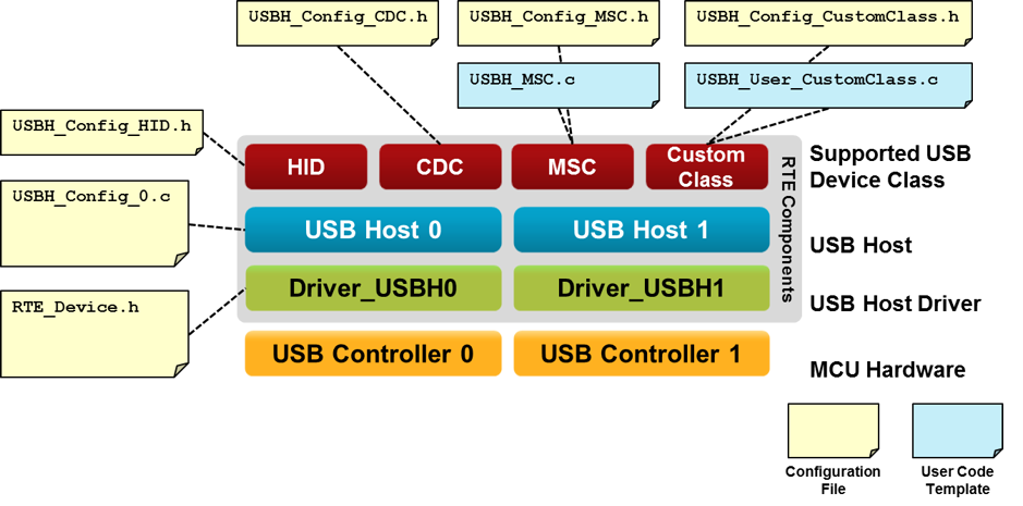
The following picture shows the relationships of the RTE Components with the microcontroller's USB Host peripheral (USB Controller). RTE Components provide configuration files and user code templates. Configuration files configure the RTE Components, hardware interfaces, memory resources and USB Host parameters. User code templates provide the skeleton for implementing support for different USB Device classes.

usb_host_blocks_config_files.png
USB Host Structure

Create an USB Host Application

The steps to create a microcontroller application that functions as an USB Host are:

  1. Select RTE Components that are required for your application.
  2. Enable and configure the USB Host Driver.
  3. Configure the USB Host that connects the USB Middleware to the microcontroller USB peripheral.
  4. Configure the System Resources according to the USB Host component's Resource Requirements.
  5. Configure the parameters of the attached USB Devices.
  6. Implement the Application Code using code templates that are provided to support various USB Device Classes.

RTE Component Selection

The RTE Component selection is done in a few steps:

  1. From the USB Component:
    • Select USB:CORE that provides the basic functionality required for USB communication.
    • Set USB:Host to '1'. This creates one USB Host for communication with attached USB Devices.
    • Select the desired support for USB Classes (HID/MSC/CDC/Custom Class). For example, select USB:Host:HID to support HID Class Devices only.
  2. From the Drivers Component:
    • Select an appropriate USB Host driver suitable for your application.
  3. From the Device Component:
    • Additional device specific drivers may be required according to the validation output.
  4. From the CMSIS Component:
    • Select the CMSIS:CORE to provide the core interface to the processor.
    • Select a suitable CMSIS:RTOS that is a required for the USB Component.
USBH_RTE.png
RTE Component Selection

USB Driver and Controller

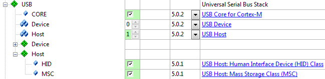
The USB Host Driver and the USB Controller of the microcontroller need to be correctly configured. In particular this means:

  • The USB Host Driver selected under the Drivers Component is typically configured with the RTE_Device.h configuration file. While this file provides multiple options, it is typically sufficient to enable the USB Host peripheral related to this driver. Some microcontrollers may require settings that related to a physical layer interface (PHY), the USB VBUS power and Overcurrent protection.
  • The USB Controller of the microcontroller needs typically specific clock settings. Consult the user's guide of the microcontroller to understand the requirements. Alternatively you may copy the setup of an USB Host example that is provided for various evaluation boards.

USB Host Configuration

The USBH_Config_n.c file contains additional settings for the specific USB Host:

  • The Driver Number is set according to the selected USB Controller. For single USB Device Controllers it will be '0'.
  • Some microcontrollers can make use of different hardware Controller Interfaces. Consult the user's guide of the selected microcontroller to choose the correct setting.

Refer to Configuration for a detailed list of all available settings.

System Resource Configuration

For proper operation, the USB Host Component requires some system configuration settings. The requirements are:

  • Additional stack size of 512 bytes. This can be configured in the device's startup_device.s file (Stack_Size).
  • The USB Host component uses CMSIS-RTOS threads. Depending on the number of instances, you need to configure additional settings in the RTX_Conf_CM.c file.

For more information, check the USB Host component's Resource Requirements section.

Configuration of Attachable USB Devices

In the USBH_Config_HID.h, USBH_Config_MSC.h, USBH_Config_CDC.h, or USBH_Config_CustomClass.h you can specify the number of concurrent USB Devices that the USB Host will support. This has an impact on the amount of memory that will be reserved in your application for the attachment of USB Devices. The USB Host Examples shows how to configure an USB Host to interact with different HID, MSC or CDC peripheral devices.

User Code Implementation

User code template files provide function templates to support various USB Device Classes on the USB Host. The available functions are explained in the Reference section of the USB Host Component. These routines can be adapted to the needs of the microcontroller application, in case different then default functionality is needed.

The following templates are available for the USB Host component:

Template Name Purpose
USBH_MSC.c Required functions to support MSC devices. The template can be found here.
USBH_PL2303.c Required functions to support the Prolific PL2303 USB to serial RS232 adapter. The template can be found here.
USBH_User_CustomClass.c Required functions to support any USB Device class. The template can be found here.