 |
Network Component
Version 6.6
MDK-Professional Middleware for IP Networking
|
|
Network Component
Version 6.6
MDK-Professional Middleware for IP Networking
|
The steps to create a microcontroller application that uses TCP/IP communication are:
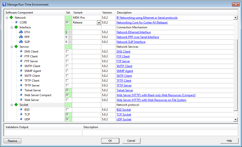
Only a few steps are necessary to complete the RTE Component selection:
The Network Device Driver and the Network Controller of the microcontroller need to be correctly configured. This means:
All configuration files for the Network Component are listed in the Project window below the Component Class "Network".
The Network Core configuration file Net_Config.c contains the setting for the Local Host Name. This is a name under which the network device can be accessed on a local area network (LAN). It usually requires a DHCP server to be present in the LAN. This name is very useful if you don't know the IP address that has been assigned to your device by the DHCP server.
The Memory Pool Size specifies the amount of RAM in bytes allocated for the memory pool. The buffers for the network packets are allocated from this memory pool. Usually, the default value of 12000 bytes is sufficient.
The Network Interface configuration files Net_Config_Interface_0.h contain the general IP address settings. You also need to specify the hardware driver number for the used interface. In case of Ethernet for example, this is usually 0. But if you are using SLIP or PPP over a serial connection, you need to specify the hardware driver number of the exact UART you wish to use. All settings for the different interfaces are described here:
Usually, the needs of most applications are served by using the default settings for the sockets. Of course, there are configuration files for all three socket types that are specified in
The configuration files for all the Network Services are explained in the respective Services section.
For proper operation, the Network Component requires some system configuration settings. The requirements are:
Stack_Size).eth_thread) when Ethernet Interface is enabled. So you need to increase the number of concurrent running threads by 1. The default thread stack size should be at least 512 Bytes. Also, User Timers need to be enabled. All these changes must be done in the be done in the RTX_Conf_CM.c file.For more information, check the Network component's Resource Requirements section.
User code template files provide access to all functions that are required to communicate over the Network. The available functions are explained in the Reference section of the Network Component. These routines can be adapted to the needs of the microcontroller application, in case more functionality is needed.
The following templates are available for the Network component:
| Template Name | User Functions |
|---|---|
| DNS_Client.c | dns_cbfunc (Callback function for notification about DNS client events), resolve_host (DNS resolving process) |
| FTP_Client_UIF.c | ftp_client_request (Request parameters for FTP client session), ftp_client_notify (Notify the user application when FTP client operation ends) |
| FTP_Server_Access.c | ftp_accept_client (Accept or deny connection from remote FTP client) |
| FTP_Server_Event.c | ftp_server_notify (Notify the user application about events in FTP server service) |
| FTP_Server_Multiuser.c | ftp_check_username (Check if an user account exists), ftp_check_password (Check user account password), ftp_file_access (Check if remote user is allowed to access a file) |
| HTTP_Server_Access.c | http_accept_client (Accept or deny connection from remote HTTP client) |
| HTTP_Server_CGI.c | cgi_process_query (Process query string received by GET request), cgi_process_data (Process data received by POST request), cgi_script (Generate dynamic web data from a script line) |
| HTTP_Server_Error.c | http_error (Define HTTP error messages) |
| HTTP_Server_Multiuser.c | http_check_account (Check if an user account exists), http_file_access (Check if remote user is allowed to access a file) |
| SMTP_Client_UIF.c | smtp_client_request (Request parameters for SMTP client session), smtp_client_notify (Notify the user application when SMTP client operation ends), smtp_client_accept_authentication (Accept or deny authentication requested by SMTP server) |
| SNMP_Agent_MIB.c | snmp_mib (MIB data table) |
| TCP_Socket_Client.c | tcp_cb_client (Notify the user application about TCP socket events), send_data (Connect to TCP server and send data) |
| TCP_Socket_Server.c | tcp_cb_server (Notify the user application about TCP socket events) |
| Telnet_Server_Access.c | telnet_accept_client (Accept or deny connection from remote Telnet client) |
| Telnet_Server_Multiuser.c | telnet_check_username (Check if an user account exists), telnet_check_password (Check user account password) |
| Telnet_Server_UIF.c | telnet_server_message (Request message for Telnet server session), telnet_server_message_poll (Poll the upper-layer user application for unsolicited messages), telnet_server_process (Process a command and generate response) |
| TFTP_Client_UIF.c | tftp_client_notify (Notify the user application when TFTP client operation ends) |
| TFTP_Server_Access.c | tftp_accept_client (Accept or deny connection from remote TFTP client) |
| UDP_Socket.c | udp_cb_func (Notify the user application about UDP socket events), send_udp_data (Send UDP data to destination client) |
Each embedded Ethernet device must have a unique MAC address, IP address, and hostname. This is very important when multiple devices are connected to the same LAN. Otherwise, network collisions might occur, network communications on a local LAN might be disturbed, and the system might not work.
You can use the same application code for serial production of embedded devices. The runtime configuration feature allows you to read configuration parameters from the EEPROM and configure the Ethernet network interface for each embedded device differently.
In the Manage Run-Time Environment window, the Network Core can be configured for two different variants:
To enable debugging with the Network Component, simply choose the Debug variant in the Manage Run-Time Environment window:
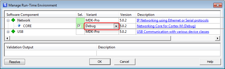
All necessary files, such as the Net_Debug.c file and the debug library will be automatically added to your project.
The system is made up of several modules that output debug messages. It is possible to configure the debug output for each module separately. This can be done in the Net_Debug.c file. There are three debug levels available:
| Level | Description |
|---|---|
| Off | The debug messages for the selected module are disabled. |
| Errors Only | Only error messages are output. This mode is useful for error tracking. |
| Full Debug | In this mode, all debug messages are output. |
The following debug options are available:
The owner module of the displayed debug message is identified by the message prefix. The following system and application modules are configurable for debugging:
| ID | Module | Description |
|---|---|---|
| MEM | Memory Management Debug | Allocates and releases frame buffers. |
| ETH | Ethernet Debug | Handles Ethernet link. |
| PPP | PPP Debug | Handles serial line direct or modem connection PPP link. |
| SLIP | SLIP Debug | Handles serial line direct or modem connection SLIP link. |
| ARP | ARP Debug | Handles Ethernet MAC address resolution and caching. |
| IP | IP Debug | Processes the IP network layer. |
| ICMP | ICMP Debug | Processes ICMP messages. Best known example is the ping. |
| IGMP | IGMP Debug | Processes IGMP messages, Hosts groups and IP Multicasting. |
| UDP | UDP Debug | Processes UDP frames. |
| TCP | TCP Debug | Processes TCP frames. |
| NBNS | NBNS Debug | The NetBIOS Name Service maintains name access to your hardware. |
| DHCP | DHCP Debug | Handles automatic configuration of IP address, Net mask, Default Gateway, and Primary and Secondary DNS servers. |
| DNS | DNS Debug | Handles the resolution of the IP address from a host name. |
| SNMP | SNMP Debug | Manages devices on IP network. |
| SNTP | SNTP Debug | Manages clock synchronization over the network. |
| BSD | BDS Debug | Processes TCP and UDP frames via standard BSD Sockets API. |
| HTTP | HTTP Server Debug | Delivers web pages on the request to web clients. |
| FTP | FTP Server Debug | Manages the files stored on the server and serves the file requests received from the clients. |
| FTPC | FTP Client Debug | Connects to FTP server to transfer files on the server, and to manage files stored on the server. |
| TNET | Telnet Server Debug | Allows remote clients to control the system using the command line interface. |
| TFTP | TFTP Server Debug | A simple service which allows you to send files to or read files from the server. |
| TFTPC | TFTP Client Debug | Connects to TFTP server to send or receive files. |
| SMTP | SMTP Client Debug | Connects to SMTP server to send emails. |
An example of the debug output is:
In the above example, Ethernet, IP and TCP debug messages are enabled:
Debug messages are output to a standard IO port. The sendchar function outputs a single character. If required, you can customize this function to send the debug messages to some other device. In most cases, a serial UART is used to print out the debug messages.
The localhost is the standard host name given to the address of the loopback network interface. The IP address of the localhost is 127.0.0.1. The packets, destined to the localhost address, are routed back internally by the IP layer of the Network Component.
Using the loopback interface is useful for testing software, since it bypasses local network interface hardware. Connecting to locally hosted network services using loopback addresses puts less of a load on network resources.
You can use the local host IP address to communicate between different applications using the socket interface on the same system, for example between a FTP server and FTP client. The FTP client connects to FTP server and manage files on FTP server using the localhost address. Of course the files are manipulated locally on the same system. No IP packets actually appear on any of the hardware interfaces.

