|
||
| Products Download Events Support Videos | ||

Technical Support
On-Line Manuals
MCBTSX1001 User's Guide
Configuring the MCBTSX1001
The MCBTSX1001 Evaluation Board is configured using 18 jumpers. The MCBTSX1001 Board ships with the following configuration:
Analog Input Configuration
| Jumper | State | Description |
|---|---|---|
| JP1 |
POT* | Selects the potentiometer for ADC input. |
| JP2 |
POT* | Selects the potentiometer for ADC input. |
| JP3 |
ON* | Grounds negative input to FDOA1 when J1 input bypasses LNA0 and LNA1. |
| JP5 |
AIN* | Connects the positive output of FDOA1 to the positive ADC input. |
| JP6 |
OFF* | Provides a 5 VDC microphone bias at Audio Input jack J1. |
| JP9 |
AIN* | Connects the negative output of FDOA1 to the negative ADC input. |
| JP11 VREF 0/1 | 1* | Provides a buffered 1.65 VDC voltage reference for FDOA1 input. |
| JP13 JACK |
ON* | Both jumpers ON connect the Low Noise op amps LNA0 and LNA1 to Audio Input jack J1. See the diagram below. |
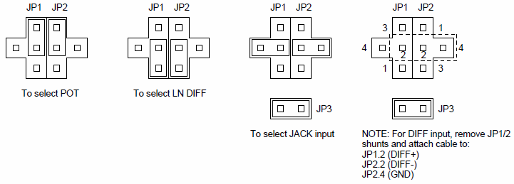
The position of jumpers JP1 and JP2 control the input to the ADC from 1 of 3 sources:
- The potentiometer (R2),
- The MIC jack (J1) using LNA0 and LNA1, or
- The MIC jack (J1) but bypassing LNA0 and LNA1.
Jumpers JP1 and JP2 must be positioned in 1 of the 4 configurations shown in the diagram below.
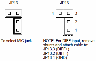
The 2 jumpers at J13 normally connect the MIC jack (J1) to LNA0 and LNA1. You may remove these jumpers to cable directly to these LNA inputs, as show below.
Analog Output Configuration
| Jumper | State | Description |
|---|---|---|
| JP4 |
AOUT* | Connects the positive output of FDOA0 to SEOA0 input. |
| JP7 S/J |
S* | Selects the on-board speaker for audio output. |
| JP8 |
AOUT* | Connects the negative output of FDOA0 to SEOA0 input. |
| JP10 Speaker |
ON* | Enables the Op Amp output to ADC input. |
| JP12 VREF 0/1 |
1* | Provides a buffered 1.65 VDC (VDD/2) voltage reference for the single-ended output amplifier. |
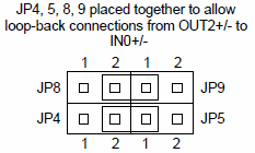
Loopback Configuration
Jumpers JP4, JP5, JP8 and JP9 are positioned together so they may be jumpered for loopback operation. See the diagram below.
Serial Communications Configuration
| Jumper | State | Description |
|---|---|---|
| JP14 |
COM* | UART RTS uses the RS232 serial interface. |
| JP15 |
COM* | UART CTS uses the RS232 serial interface. |
| JP16 |
COM* | UART RX uses the RS232 serial interface. |
| JP17 |
COM* | UART TX uses the RS232 serial interface. |
Oscillator Control
| Jumper | State | Description |
|---|---|---|
| JP19 OSC EN |
ON* | Enables the 44mHz oscillator (U9). |
* Factory setting of MCBTSX1001.
ProductsDevelopment Tools |
Hardware & Collateral |
Downloads |
Support |
Contact |