 |
USB Component
Version 6.6
MDK-Professional Middleware for USB Device and Host
|
|
USB Component
Version 6.6
MDK-Professional Middleware for USB Device and Host
|
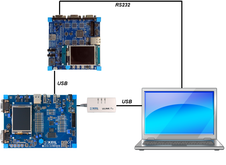
This example application shows how to connect an USB CDC ACM Device to a development board. It is a simple demonstration on how to send data from the USB Host to the attached USB CDC ACM Device. Here, the USB Host sends "Test!" to the USB CDC ACM Device and stores all incoming messages from the device in the variable receive_buf.
The following picture shows an exemplary connection of the development board and an USB CDC ACM Device implemented on another development board. This USB CDC ACM Device is connected to a PC via RS232 to check incoming messages.
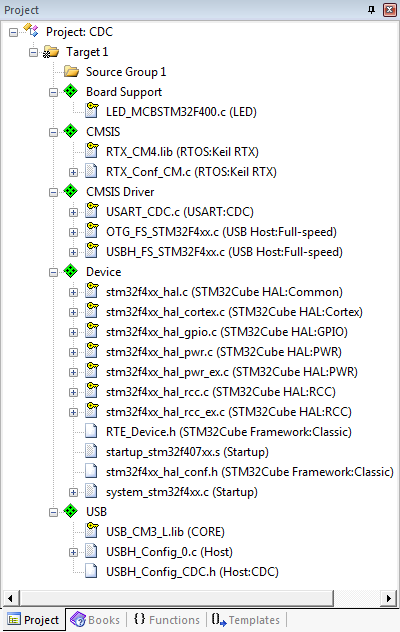
Create a new project in MDK. In this example, we are using the MCBSTM32F400 board with the STM32F407IGHx device. In the Manage Run-Time Environment window, select the following components:
Click the Resolve button and then OK. Your Project should look like this:
#include <stdio.h>                      /* Standard I/O .h-file               */
#include <ctype.h>                      /* Character functions                */
#include <string.h>                     /* String and memory functions        */

#include "cmsis_os.h"                   /* CMSIS RTOS definitions             */
#include "rl_usb.h"                     /* RL-USB function prototypes         */

#include "Terminal.h"
#include "Board_LED.h"

#include "Driver_USART.h"

#include "stm32f4xx_hal.h"

extern bool USBH_SerialCheckReady (void);

/* UART Driver */
extern ARM_DRIVER_USART       Driver_USART9;
#define ptrUART_USB         (&Driver_USART9)

osThreadId  con_discon_thread_id;
bool        connected;

extern uint32_t os_time;

uint32_t HAL_GetTick(void) {
  return os_time;
}

/* System Clock Configuration */
void SystemClock_Config(void) {
  RCC_OscInitTypeDef RCC_OscInitStruct;
  RCC_ClkInitTypeDef RCC_ClkInitStruct;

  /* Enable Power Control clock */
  __PWR_CLK_ENABLE();

  /* The voltage scaling allows optimizing the power consumption when the
     device is clocked below the maximum system frequency (see datasheet). */
  __HAL_PWR_VOLTAGESCALING_CONFIG(PWR_REGULATOR_VOLTAGE_SCALE1);

  /* Enable HSE Oscillator and activate PLL with HSE as source */
  RCC_OscInitStruct.OscillatorType = RCC_OSCILLATORTYPE_HSE;
  RCC_OscInitStruct.HSEState = RCC_HSE_ON;
  RCC_OscInitStruct.PLL.PLLState = RCC_PLL_ON;
  RCC_OscInitStruct.PLL.PLLSource = RCC_PLLSOURCE_HSE;
  RCC_OscInitStruct.PLL.PLLM = 25;
  RCC_OscInitStruct.PLL.PLLN = 336;
  RCC_OscInitStruct.PLL.PLLP = RCC_PLLP_DIV2;
  RCC_OscInitStruct.PLL.PLLQ = 7;
  HAL_RCC_OscConfig(&RCC_OscInitStruct);

  /* Select PLL as system clock source and configure the HCLK, PCLK1 and PCLK2
     clocks dividers */
  RCC_ClkInitStruct.ClockType = RCC_CLOCKTYPE_SYSCLK | RCC_CLOCKTYPE_PCLK1 |
                                RCC_CLOCKTYPE_PCLK2;
  RCC_ClkInitStruct.SYSCLKSource = RCC_SYSCLKSOURCE_PLLCLK;
  RCC_ClkInitStruct.AHBCLKDivider = RCC_SYSCLK_DIV1;
  RCC_ClkInitStruct.APB1CLKDivider = RCC_HCLK_DIV4;
  RCC_ClkInitStruct.APB2CLKDivider = RCC_HCLK_DIV2;
  HAL_RCC_ClockConfig(&RCC_ClkInitStruct, FLASH_LATENCY_5);
}

/*------------------------------------------------------------------------------
 *        UART Done Callback
 *----------------------------------------------------------------------------*/
void UART_Done (uint32_t event) {
  switch (event) {
    case ARM_USART_EVENT_SEND_COMPLETE:
      LED_On(1);
      break;
    case ARM_USART_EVENT_RECEIVE_COMPLETE:
      LED_On(2);
      break;
  }
}

/*------------------------------------------------------------------------------
 *        USB Host Serial Receive Thread
 *----------------------------------------------------------------------------*/
void USBH_Serial_ReceiveThread (void const *arg) {
  uint8_t receive_buf[64];
  while (1) {
    ptrUART_USB->Receive (receive_buf, 64);
    osDelay(1000);
  }
}
osThreadDef(USBH_Serial_ReceiveThread, osPriorityNormal, 1, NULL);

/*------------------------------------------------------------------------------
 *        USB Host Thread
 *----------------------------------------------------------------------------*/
void USBH_Thread (void const *arg) {
  static bool con = false;

  USBH_Initialize (0);                        /* Initialize USB Host 0        */

  while (1) {
    if ((USBH_CDC_ACM_GetDeviceStatus(0) == usbOK) ^ con) {
      if (!con) {
        con = true;
        LED_On(0);
        osDelay(1000);

        /* Initialize and configure UART <-> USB Bridge */
        ptrUART_USB->Initialize  (UART_Done);
        ptrUART_USB->PowerControl(ARM_POWER_FULL);
        ptrUART_USB->Control     (ARM_USART_MODE_ASYNCHRONOUS |
                                  ARM_USART_DATA_BITS_8       |
                                  ARM_USART_PARITY_NONE       |
                                  ARM_USART_STOP_BITS_1       |
                                  ARM_USART_FLOW_CONTROL_NONE ,
                                  115200                      );
        ptrUART_USB->Control     (ARM_USART_CONTROL_TX, 1);
        ptrUART_USB->Control     (ARM_USART_CONTROL_RX, 1);
        ptrUART_USB->Send        ("Test!\r\n", 7);
        osThreadCreate (osThread(USBH_Serial_ReceiveThread), NULL);
      } else {
        con = false;
        LED_Off(0);
      }
    } else {
      osDelay(1000);
    }
  }
}
osThreadDef(USBH_Thread, osPriorityNormal, 1, NULL);

/*------------------------------------------------------------------------------
 *        Application
 *----------------------------------------------------------------------------*/
int main (void) {

  HAL_Init();                                 /* Initialize the HAL Library   */
  SystemClock_Config();                       /* Configure the System Clock   */

  LED_Initialize           ();

  con_discon_thread_id =   osThreadCreate (osThread(USBH_Thread), NULL);

  while (1) {
    osDelay(100);
  }
}
/*------------------------------------------------------------------------------
 * MDK Middleware
 * Copyright (c) 2004-2014 ARM Germany GmbH. All rights reserved.
 *------------------------------------------------------------------------------
 * Name:    Terminal.h
 * Purpose: File manipulation example terminal definitions
 *----------------------------------------------------------------------------*/

#include <stdbool.h>

enum {BACKSPACE = 0x08,
      LF        = 0x0A,
      CR        = 0x0D,
      CNTLQ     = 0x11,
      CNTLS     = 0x13,
      ESC       = 0x1B,
      DEL       = 0x7F };

/* External functions */
extern bool getline  (char *buf, int bufsz);
Before building the project, you need to edit these configuration files:
Before building and downloading the project to the target, make sure that the correct debugger is set in the Options for Target dialog (ALT + F7). You may then build and download the example project to the evaluation board using the µVision commands:
After these steps, the project should start executing on your evaluation kit. In case of errors, refer to the Evaluation Board User's Guide for configuration information.

