USB Component  Version 6.17.0
MDK Middleware for USB Device and Host Communication
USB Device

This chapter describes the software structure of the USB Device Component and its use for creating applications. The USB Device Component simplifies the software development of microcontroller systems that interface to a USB Host.

Attributes of the USB Device Component:

  • Supports Low-Speed, Full-Speed and High-Speed.
  • Supports standard USB Classes with multiple device class instances.
  • Supports composite devices. Combine USB Device Classes to create a composite device.
  • Supports multiple USB Devices on a single microcontroller with more than one USB Device controller.
  • Provides for implementing the USB Device functionality.
  • Provides an user-friendly configuration file for each device class to generate USB Descriptors.
  • Flexibly assigns USB Endpoints to the microcontroller USB Device peripheral.
  • Provides Examples to show the use of the software stack.

For interfacing to an USB Host Computer, additional software may be required. Page USB Host Computer Applications shows an example for such a software running on Windows PCs.

RTE Components

The picture shows the relationship between RTE Components and the microcontroller's USB Device peripheral (USB Controller). RTE Components provide configuration files and user code templates. Configuration files configure the RTE Components, hardware interfaces, memory resources and USB Device driver parameters. They can have an impact on multiple RTE Components (for example RTE_Device.h configures the USB Controller 0 and Driver_USBD0). User code templates provide the skeleton for implementing the USB Device functionality.

The grey area around the RTE Components USB Device 1 and Driver_USBD1, as well as USB Controller 1 means that these components are optional and can only be used if a microcontroller device has multiple USB controllers present. If this is the case, an USB Device Class can be connected to any of the USB Device Instances.

USB Device Structure

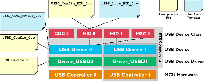
USB Device peripherals can have one or more of the following USB Device Classes:

  • Audio Device Class (ADC) is used to exchange streaming audio data between the USB Host and the USB Device.
  • Communication Device Class (CDC) provides virtual communication port functionality to the USB Host.
  • Human Interface Device (HID) is typically used to implement a keyboard, joystick, or mouse. The HID Class can be also used for low bandwidth data exchange.
  • Mass Storage Class (MSC) is used to connect various storage devices to an USB Host. Mass Storage Class media can be an SD card, internal or external Flash memory, or RAM.
  • Custom Class is used to implement either a standard or a vendor specific USB Device Class.

Generic information about USB Device Classes can be found on the USB-IF's Approved Class Specification Documents page.

Multiple RTE Component instances can interface with more than one USB Controller or can implement multiple USB Device Classes. RTE Component instances are numbered. The number is appended to the RTE Component name, related configuration files, and user code templates. Each RTE Component has a separate configuration file. For example, for HID 0 and HID 1 the configuration files have the name USB_Config_HID_0.h and USB_Config_HID_1.h.

Note
The default configuration settings are pre-configured for one instance of an USB Device or USB Device Class in a non-composite device peripheral. For other combinations the settings need to be edited to ensure proper operation. The USB Composite Device example shows how to implement and configure a composite devices

Create an Application

The steps to create a microcontroller application that uses USB communication with an USB Device controller are:

  1. Select RTE Components along with the USB Device Classes that are required for your application.
  2. Enable and configure the USB Device Driver.
  3. Configure the USB Device that connects the USB Middleware to the microcontroller USB peripheral.
  4. Configure USB Device Class Configuration and USB Endpoint Settings for each selected USB Device Class and instance.
  5. Configure the System Resources according to the USB Device component's Resource Requirements.
  6. Implement the Application Code using code templates that are provided for the USB Device Classes.
  7. If required by your application, you can change the default USB Device descriptors.
  8. Debug you application using the built-in mechanisms of the USB Component.

For interfacing to an USB Host computer, standard USB Device Classes drivers can be used. This may require additional software development for the USB Host application. An exemplary application for interfacing to an USB HID Device is explained here.

RTE Component Selection

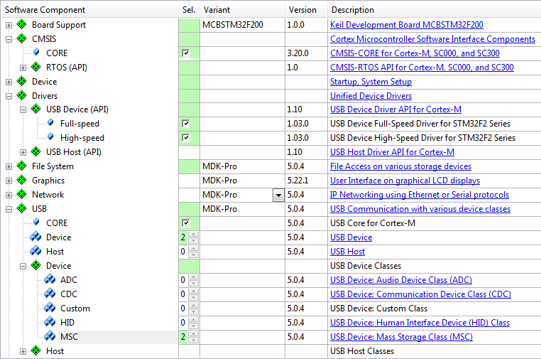
Only a few steps are necessary to complete the RTE Component selection:

  1. From the USB Component:
    • Select USB:CORE that provides the basic functionality required for USB communication.
    • Set USB:Device to '1'. This creates one USB Device for communication with the USB Host.
    • Select the desired USB Classes (HID, MSC, CDC, ADC, or Custom Class). For example, set USB:Device:HID to '1' to create a single HID Class Device. If you select more than one class or multiple instances of the same class on the same device, you will create a Composite USB Device.
  2. From the Drivers Component:
    • Select an appropriate USB Device driver suitable for your application.
  3. From the Device Component:
    • Additional device specific drivers may be required according to the validation output.
  4. From the CMSIS Component:
    • Select the CMSIS:CORE to provide the core interface to the processor.
    • Select a suitable CMSIS:RTOS or CMSIS:RTOS2 that is a required for the application.
RTE Component Selection
Note
  • Most microcontrollers have only one USB Controller implemented in hardware and only one driver Driver_USBD0 is available. In this case, only one USB:Device can be selected to generate USB Device 0.
  • On a single USB Device 0 an USB Composite Device may be implemented that combines multiple USB Device Classes.
  • When a microcontroller implements multiple USB Controllers an additional USB Device 1 can be generated by setting USB:Device to '2'.

USB Driver and Controller

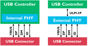
The USB Device Driver and the USB Controller of the microcontroller need to be correctly configured. In particular this means:

  • The USB Device Driver selected under the Drivers Component is typically configured with the RTE_Device.h configuration file. While this file provides multiple options, it is typically sufficient to enable the USB Device peripheral related to this driver. Some microcontrollers may require settings that are related to a physical layer interface (PHY). The picture below shows two possible variants. Either, the USB PHY is integrated into the controller, or an external chip is used for providing the USB signal lines:
USB Controller and PHY Setups
  • The USB Controller of the microcontroller typically needs specific clock settings. Consult the user's guide of the microcontroller to understand the requirements. Alternatively, you may copy the setup of an USB Device example (in case your hardware setup is similar to that of the chosen evaluation boards).

USB Device Configuration

The configuration file USBD_Config_n.c is listed in the Project Windows under the Component USB and contains a number of important settings for the specific USB Device.

  • The Driver_USBD# number is set according to the selected USB Controller. This specifies which driver will be used for the USB Device determining the pin-out as well. For single USB Device Controllers it will be '0'.
  • High-Speed may be selected if supported by the USB Controller.
  • The Vendor ID (VID) needs to be set to a private VID. The default Vendor ID is owned by Keil and must not be used for actual products. Please visit USB-IF for more information on how to apply for a valid Vendor ID.
  • Every device variant needs an unique Product ID. Together with the VID, it is used by the Host computer's operating system to find a driver for your device.
  • The Device Release Number will be shown in Windows and Linux systems as “Firmware Revision”. The number will be interpreted as “binary coded decimal”, meaning that 0x0101 will be shown as firmware revision 1.01.
  • The Manufacturer, Product and the Serial Number String can be set to identify the USB Device on the USB Host.

Refer to USB Core Configuration for more configuration options of the USB Device.

Note
You can configure the USB Device at run-time using the functions from the USB Device Core API. The section USB Device Core explains the details. Implement the run-time specific behavior with the user code template USBD_User_Device_n.c.

USB Device Class Configuration and USB Endpoint Settings

The USB Device Class Parameters and Endpoint Settings are configured in separate files for each USB Device Class and separately for each instance. The configuration files contain Device Class specific Endpoint Settings Numbers and are listed in the Project Window under the Component USB.

  • USBD_Config_ADC_n.h configuration for Audio Device Class (ADC).
  • USBD_Config_CDC_n.h configuration for Communication Device Class (CDC).
  • USBD_Config_HID_n.h configuration for Human Interface Device Class (HID).
  • USBD_Config_MSC_n.h configuration for Mass Storage Device Class (MSC).
  • USBD_Config_CustomClass_n.h configuration for Custom Class.

Each USB Endpoint can only be used once on the same USB Device. It has to be made sure that the different USB Device Classes or multiple instances of the same USB Device Class use different Endpoints. The default configuration supports applications that use a single USB Device Class. The remaining parameters are specific settings that configure parameters for USB communication speed and the USB Device Class.

System Resource Configuration

For proper operation, the USB Device Component requires some system configuration settings. The requirements are:

  • Additional stack size of 512 bytes. This can be configured in the device's startup_device.s file (Stack_Size).
  • The USB Device Component uses CMSIS-RTOS threads. In case RTX v5 is used no changes to RTX settings are necessary as all resources are allocated statically. In case RTX v4 is used you need to change following settings in file:
    • Increase the Number of concurrent running user threads by number of threads required by USB Device
    • Increase the Number of threads with user-provided stack size by number of threads required by USB Device
    • Increase Total stack size [bytes] for threads with user-provided stack size by size of threads required by USB Device
    • Enable User Timers if HID class is used

For more information, check the USB Device component's Resource Requirements section.

User Code Implementation

files provide function templates used to implement USB Device Class functionality. The available functions are explained in the Reference section of the USB Component. These routines can be adapted to the needs of the microcontroller application, in case different then default functionality is needed.

The following templates are available for the USB Device component:

Template Name Purpose
USBD_User_ADC_n.c Required functions to create an ADC device.
USBD_User_CDC_ACM_n.c Required functions to create a CDC (ACM) device.
USBD_User_CDC_ACM_RNDIS_VETH_n.c Required functions to create a CDC (ACM) RNDIS virtual Ethernet device.
USBD_User_CDC_ACM_RNDIS_ETH_n.c Required functions to create a CDC (ACM) RNDIS and Ethernet bridge device (Ethernet-over-USB).
USBD_User_CDC_ACM_UART_n.c Required functions to create a CDC (ACM) device demonstrating a USB <-> UART bridge.
USBD_User_CDC_NCM_n.c Required functions to create a CDC (NCM) device.
USBD_User_CDC_NCM_ETH_n.c Required functions to create a CDC (NCM) device (Ethernet-over-USB).
USBD_User_CustomClass_n.c Required functions to create a device supporting a custom USB Device class.
USBD_User_Device_n.c Required functions for run-time configuration of the USB Device.
USBD_User_SerNum_n.c Example for run-time configuration: Changing the serial number of the USB Device.
USBD_User_HID_n.c Required functions to create a HID device.
USBD_User_HID_Mouse_n.c Implements functions to create a USB HID device acting as a mouse pointer input device.
USBD_User_MSC_n.c Required functions to create a MSC device.
USBD_MSC_n.c Shows how to get access to storage media either from the application/File System or from the USB host.

Changing Default USB Descriptors

If there are different requirements regarding the USB Descriptors than the USB Component allows, a user can change any or all of the default USB descriptors. Default descriptors are the ones that library creates based on Device and Classes configuration file settings and are located in code memory.

The descriptors can be changed in two of the following ways:

  • Static change

Static change of descriptors can be done to replace default descriptors if they will not change at runtime. The descriptors can be easily overridden by user code by creating descriptors with the same name.

USB Device Descriptor Purpose
const uint8_t usbdn_ep0_descriptor[] Control Endpoint 0 descriptor
const uint8_t usbdn_device_descriptor[] USB Device descriptor
const uint8_t usbdn_string_descriptor[] String descriptors
const uint8_t usbdn_device_qualifier_fs[] Device qualifier for low/full-speed
const uint8_t usbdn_device_qualifier_hs[] Device qualifier for high-speed
const uint8_t usbdn_config_descriptor_fs[] Configuration descriptor for low/full-speed
const uint8_t usbdn_config_descriptor_hs[] Configuration descriptor for high-speed
const uint8_t usbdn_other_speed_config_descriptor_fs[] Other speed configuration descriptor for low/full-speed
const uint8_t usbdn_other_speed_config_descriptor_hs[] Other speed configuration descriptor for high-speed
Note
  • n in usbdn_ represents the USB Device instance. So for the USB Device 0 instance, you have to use usbd0_...

Code Example

// Statically change USB Device 0 Device Descriptor
const uint8_t usbd0_device_descriptor[] = {
18U, // bLength = 7 bytes
1U, // bDescriptorType = 1 = Device Descriptor Type
0U,2U, // bcdUSB = 2.00 (little-endian)
0U, // bDeviceClass = 0 = Defined in interface
0U, // bDeviceSubClass = 0 = Defined in interface
0U, // bDeviceProtocol = 0 = Defined in interface
64U, // bMaxPacketSize = 64
0x51U,0xC2U, // idVendor = 0xC251 (little-endian)
0x34U,0x12U, // idProduct = 0x1234 (little-endian)
0U,1U, // bcdDevice = 1.00 (little-endian)
0U, // iManufacturer = 0 = No Manufacturer string
0U, // iProduct = 0 = No Product string
0U, // iSerialNumber = 0 = No Serial Number string
1U // bNumConfigurations = 1 = 1 configuration
};
  • Dynamic change

Dynamic change of descriptors can be done to change descriptors at runtime. The struct usbd_desc_t contains the required information. It is stored in RAM and contains pointers to the USB descriptors. If you change the pointers in the structure to the point to the externally created ones, you can change the descriptors at runtime.

The actual variable names of the structures holding descriptor pointers are usbdn_desc (n indicating the USB Device instance number). The following code example shows how to override the device descriptor for the USB Device 0 (usbd0_desc):

Code Example

// Dynamically change USB Device 0 Device Descriptor
const uint8_t dev0_device_descriptor[] = {
18U, // bLength = 7 bytes
1U, // bDescriptorType = 1 = Device Descriptor Type
0U,2U, // bcdUSB = 2.00 (little-endian)
0U, // bDeviceClass = 0 = Defined in interface
0U, // bDeviceSubClass = 0 = Defined in interface
0U, // bDeviceProtocol = 0 = Defined in interface
64U, // bMaxPacketSize = 64
0x51U,0xC2U, // idVendor = 0xC251 (little-endian)
0x34U,0x12U, // idProduct = 0x1234 (little-endian)
0U,1U, // bcdDevice = 1.00 (little-endian)
0U, // iManufacturer = 0 = No Manufacturer string
0U, // iProduct = 0 = No Product string
0U, // iSerialNumber = 0 = No Serial Number string
1U // bNumConfigurations = 1 = 1 configuration
};
extern usbd_desc_t usbd0_desc;
int main (void) {
...
usbd0_desc.device_descriptor = (uint8_t *)dev0_device_descriptor;
...
}
Note
For changing just serial number string use function USBD_SetSerialNumber!
For non high-speed capable device following descriptors are not important:

Debugging

USB Device Component is distributed in library form and doesn't allow direct code debug. However it can be easily configured to generate debug events and provide dynamic visibility to the component operation.

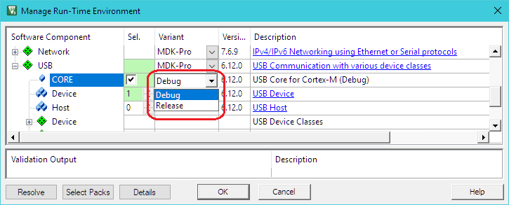
Following variants can be selected for the USB:CORE component in the Manage Run-Time Environment window:

  • Debug: this variant supports event annotations for the and makes it very easy to analyze the internal operation of the USB Device Component during application debug. Event Recorder Support below explains how to configure and use this variant.
  • Release: this variant does not include additional debugging code. Use this variant when deploying the application.

The figure below shows selection of the Debug variant.

The USB Device:Debug Events describes the events implemented in the USB Device Component.

Event Recorder Support

is a powerful tool that provides visibility to the dynamic execution of the program.

The USB Device Component generates a broad set of Debug Events for the Event Recorder and implements required infrastructure to interface with it.

To use the Event Recorder it is required to create an image with event generation support. The necessary steps are:

  1. : in the RTE management dialog select the Debug variant for the USB:CORE software component.
  2. : in the RTE management dialog enable the software component CMSIS-View:Event Recorder.
  3. Ensure that Event Recorder is initialized preferably by if CMSIS-RTOS2 RTX v5 is used, or alternatively by calling the function in the application code.
  4. Event Recorder Configuration: if necessary, adjust default Event Recorder configuration.
  5. Build the application code, download it to the target hardware and start debug session.

Now, when the USB Device generates event information, it can be viewed in the .

Event Recorder Configuration

This section describes the configuration settings for the Event Recorder. The usage requires the debug variant of the USB:CORE software component; refer to Event Recorder Support for more information.

USB Event Generation Configuration

Selecting the USB:CORE debug variant will add the file USB_Debug.c to your project. Use this file to set the event generation configuration for USB core, drivers, and device classes separately. The file is available for USB Device and Host components.

USB_Debug.c file for event generation configuration

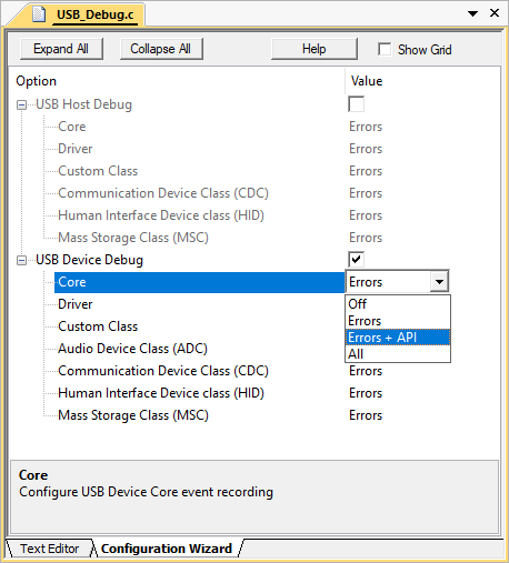
The following settings are available for event generation configuration of each module:

  • Off means no events will be generated by the module
  • Errors means only error events will be generated by the module
  • Errors + API means error and API call events will be generated by the module
  • All means all available events will be generated by the module. Besides error and API call events, this contains operation and detailed events.

Event IDs

The USB Device component uses the following event IDs:

Component Event ID
USBD_Core 0xA0
USBD_Driver 0xA1
USBD_CC 0xA2
USBD_ADC 0xA3
USBD_CDC 0xA4
USBD_HID 0xA5
USBD_MSC 0xA6