|
||
| Products Download Events Support Videos | ||
Product Information
Device Database®
Downloads
Compliance Testing
Distributors
Peripheral Simulation
For Maxim 71M6541F — Interrupts 6S/4L (Including External)
Simulation support for this peripheral or feature is comprised of:
- Dialog boxes which display and allow you to change peripheral configuration.
These simulation capabilities are described below.
Interrupt Dialog

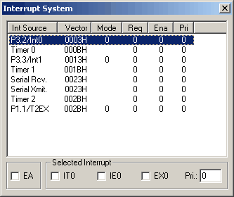
The Interrupt System dialog (available from the Peripherals menu) displays the status of all simulated MCU interrupts. The interrupt source, vector address, mode, request, priority, and enabled status are displayed. Clicking on a column header orders the interrupt list based on the selected column. You may use this dialog to manually change the interrupt configuration. Select the desired interrupt source from the list.
The Selected Interrupt group displays the control bits assigned to that interrupt. Click on the desired check box to immediately effect the change. You may even trigger an interrupt by clicking on its request bit. You may trigger an external interrupt by toggling the appropriate port pin. External interrupt 0 is triggered by either a changing edge or level on I/O PORT 3.2. You can change the state of the pin by writing to the PORT3 VTREG. The following assignments may be entered in the command window to toggle PORT 3.2.
PORT3 ^= 0x04    // Toggle PORT 3.2
PORT3 ^= 0x04    // Toggle PORT 3.2
These commands toggle the state of PORT 3.2 and then toggle it back.
ProductsDevelopment Tools |
Hardware & Collateral |
Downloads |
Support |
Contact |
