|
||
| Products Download Events Support Videos | ||
Product Information
Device Database®
Downloads
Compliance Testing
Distributors
Peripheral Simulation
For NXP (founded by Philips) LPC1112/202 — UART
Simulation support for this peripheral or feature is comprised of:
- Dialog boxes which display and allow you to change peripheral configuration.
These simulation capabilities are described below.
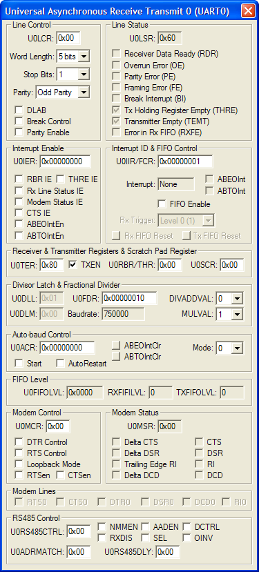
UART 0 Dialog

The Universal Asynchronous Receiver Transmitter (UART 0) Dialog configures UART 0. A UART transfers serial data to and from external devices and the ARM controller. The UART can be configured in a variety of ways to suit the external serial device.
Line Control Group
- U0LCR (Line Control Register) displays the combined control information for the following:
- Word Length selects the data character length of 5, 6, 7 or 8 bits per character.
- Stop Bits (Number of Stop Bits) selects the number of stop bits to be sent with each character.
- Parity selects odd, even or no (forced "0" or "1") parity.
- DLAB (Divisor Latch Access Bit) is set to calculate the baud rate based on the Divisor Latch register (DLL and DLM) values.
- Break Control is set to enable transmission of a Break.
- Parity Enable is set to enable parity generation and checking.
Line Status Group
- Receiver Data Ready (RDR) set when the UART 0 receives at least 1 character and the receiver hold register is not empty.
- Overrun Error (OE) set if the controller detects an overrun condition since the last status reset command.
- Parity Error (PE) set if the controller detects at least 1 false parity bit since the last status reset command.
- Framing Error (FE) set if the controller detects a framing error since the last status reset command.
- Break Interrupt (BI) is set when a Break condition occurs while receiving data.
- Tx Holding Register Empty (THRE) is set when the transmission hold register is empty.
- Transmitter Empty (TEMT) set if there are no characters in the transmitter.
- Error in Rx FIFO (RXFE) is set when the receiver detects any error (parity, framing, overrun or break).
Interrupt Enable Group
- U0IER (Interrupt Enable Register) contains the RBR, THRE and Line Status Enable bits.
- RBR IE (Receive Buffer Register Interrupt Enable) is set to enable the Receive Data Available interrupt.
- THRE IE (Transmit Hold Register Empty Interrupt Enable) is set to enable the Transmitter Empty (THRE) interrupt.
- Rx Line Status EI (Line Status Interrrupt Enable) is set to enable Line Status interrupts.
Interrupt ID & FIFO Control Group
- U0IIR/FCR (Interrupt Identification/FIFO Control Register)
- Interrupt displays the interrupt type(Line Status, THRE, RDA, Character Time-out).
- FIFO Enable (FIFO Enable) is set to clear and enable the receive and transmit FIFOs.
- Rx Trigger (Rx Trigger Level Select) sets the number of characters required to trigger a receive interrupt.
- Rx FIFO Reset clears the receive FIFO buffer.
- Tx FIFO Reset clears the transmit FIFO buffer.
Receiver & Transmitter Registers & Scratch Pad Registers Group
- U0TER (Transmitter Enable Register) contains the TXEN bit.
- TXEN Turns off UART transmitter for use with software flow control.
- U0RBR/THR (Receiver Buffer Register/Transmitter Hold Register) when receiving, is the oldest character received. When transmitting, it is the newest character to be transmitted.
- U0SCR (Scratch Pad Register) has no effect on the UART operation. It can be used for general purpose storage.
Divisor Latch & Fractional Divider Group
- U0DLL (Divisor Latch LSB Register) contains the lower 8-bit value that the MCU divides into the MCU clock (PCLK) to generate the UART baud rate.
- U0DLM (Divisor Latch MSB Register) contains the upper 8-bit value that the MCU divides into the MCU clock (PCLK) to generate the UART baud rate.
- U0FDR (Fractional Divider Register) Generates a clock input for the baud rate divider.
- Baudrate is the computed UART baud rate.
Modem Control Group
- U0MCR (Modem Control Register) contains the DTR, RTS and Loobback modem controls.
- DTR Control (Data Terminal Ready Control) is the DTR modem output level.
- RTS Control (Request To Send Control) is the RTS modem output level.
- Loopback Mode is set to perform diagnostic loopback testing.
Modem Status Group
- U0MSR (Modem Status Register) contains the following status from the modem input signals:
- Delta CTS (Delta Clear to Send) is set when the state of modem input CTS changes.
- Delta DSR (Delta Data Set Ready) is set when the state of modem input DSR changes.
- Trailing Edge RI (Trailing Edge Ring Indicator) is set when a low-to-high transition occurs on the RI input.
- Delta DCD (Delta Data Carrier Detect) is set when the state of modem input DCD changes.
- CTS (Clear To Send) is the complement of the CTS input signal.
- DSR (Data Set Ready) is the complement of the CTS input signal.
- RI (Ring Indicator) is the complement of the CTS input signal.
- DCD (Data Carrier Detect) is the complement of the CTS input signal.
Modem Lines Group This group displays the following modem signal levels.
- RTS0 Request To Send
- CTS0 Clear To Send
- DTR0 Data Terminal Ready
- DSR0 Data Set Ready
- DCD0 Data Carrier Detect
- RI0 Ring Indicator
ProductsDevelopment Tools |
Hardware & Collateral |
Downloads |
Support |
Contact |
