|
||
| Products Download Events Support Videos | ||
Product Information
Device Database®
Downloads
Compliance Testing
Distributors
Peripheral Simulation
For STMicroelectronics STR751FR2 — Power, Reset and Clock Control Unit (PRCCU)
Simulation support for this peripheral or feature is comprised of:
- Dialog boxes which display and allow you to change peripheral configuration.
- VTREGs (Virtual Target Registers) which support I/O with the peripheral.
These simulation capabilities are described below.
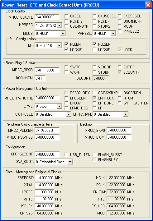
Power, Reset , CFG and Clock Control Unit (PRCCU) Dialog

Power, Reset and Clock Control Unit (PRCCU) Dialog

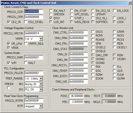
The Power, Reset, CMU and Clock Control Unit dialog configures the power saving mode, clock dividers, boot configuration and the core, memory and peripheral clocks of the ARM controller.
Clock Control & Flags
- PRCCU_CCR (Clock Control Register) contains the clock control bits.
- PRCCU_CFR (Clock Flag Register) contains the clock indicator flag bits.
- CK2_16 (CLK2/16 Select) when set, uses CLK2 (or PLL output depending on CSU_CKSEL) as the source of RCLK. If reset, CLK2 divided by 16 is used.
- CSU_CKSEL (CSU Clock Select) uses the clock from the PLL multiplier for the system clock when LOCK and VROK are set.
- EN_HALT (Enable Halt) allows the HALT bit to stop the MCU or generate a software reset.
- SRESEN (Software Reset Enable) allows a software reset (HALT bit in PRCCU_SMR) if EN_HALT is also set.
- DIV2 (OSCIN Divided by 2) is set to divide CLK by 2.
- LVD_INT (Internal LVD Reset Flag) indicates that an internal LVD reset occurred.
- EN_STOP (Stop Interrupt Masking Bit) enables the stop interrupt request.
- WFI_CKSEL (Wait For Interrupt Clock Select) is set to use CK_AF for MCLK during Low Power WFI, otherwise use CLK2/16 during Low Power WFI. Setting this bit effectively enables CKAF_SEL in WFI mode.
- STOP_I (Stop Interrupt Pending) is set when a Stop Interrupt request is pending.
- WDG_RES0 (Watchdog Reset Flag) is set when a watchdog reset occurs.
- EN_CK2_16 (CK2_16 Interrupt Masking Bit) enables the CK2_16 interrupt request.
- LPOWFI (Low Power Mode During Wait For Interrupt) is set to force the device into Low Power Mode when an Wait For Interrupt (WFI) instruction executes.
- CK2_16_I (CK2_16 Switching Interrupt Pending) is set when a C2_16 Switching Interrupt request is pending.
- SOFTRES (Software Reset Flag) is set when a software reset occurs.
- EN_LOCK (Lock Interrupt Masking Bit) enables the LOCK interrupt request.
- LOCK_I (Lock Interrupt Pending) is set when a Lock Interrupt request is pending.
- LOCK (PLL Locked) is set when the PLL is locked.
Voltage Regulator Control
- PRCCU_VRCTR (Voltage Regulator Control Register) contains the following control bits:
- VRPR (Voltage Regulator Power Reference) selects the voltage regulator reference voltage.
- VR_LPW (Voltage Regulator for Low Power WFI) is set to keep the voltage regulator on when the system enters low power mode.
- VROFF_REG is set to indicate the voltage regulator is off.
- VROK (Main Regulator OK) is set when the main voltage regulator is stable.
System Mode
- PRCCU_SMR (System Mode Register) contains the following control bits:
- WFI (Wait For Interrupt Mode) is set by the hardware to indicate an interrupt request is acknowledged by the External Interrupt Controller(EIC).
- HALT (Halt) when set, generates a software reset if SRESEN and ENHALT bits are set.
PLL Configuration
- PRCCU_PLL1CR (PLL 1 Configuration Register) contains the following control bits:
- FREEN (PLL Free Running Mode Enable) if set in conjunction with DX, provides a slow frequency back up clock selected by the CSU_CKSEL. If reset, the PLL uses the MX and DX settings.
- FREF_RANGE (Reference Frequency Range Select) is set to configure the PLL for CLK2 frequencies greater than 3MHz. If reset, CLK2 frequencies between 1.5MHz and 3MHz may be used.
- MX (PLL Multiplier) selects the multiplier (12, 16, 20 or 24) for the PLL.
- DX (PLL Output Clock Divisor) selects the PLLCK divisor (1-7).
Real Time Clock Programming
- PRCCU_RTPR (Real Time Clock Program Register) contains the following:
- RTP (Real Time Clock Programming) selects the divisor factor that determines the real-time clock frequency.
Clock Monitor Unit
- CMU_CTRL (Control Register) contains the following control bits:
- OSCS( Oscillator Stop bit) is set to stop the mail oscillator.
- RCFR (RC oscillator Frequency in Run mode) is set to select the RC oscillator in run mode.
- RCHSE (RC oscillator Hardware Stop Enable bit) is set to stop the RC oscillator the next time the device enters the Stop mode.
- SFM (Start Frequency Measurement) is set to start clock frequency measurement.
- CRFR (CMU Reset Flag Reset bit) is set to clear the CMU Reset Flag.
- RCFS (RC oscillator Frequency in Stop mode) is set to select the RC oscillator frequency the next time the device enters the Stop mode
- RCSS (RC oscillator Software Stop) is set to stop the backup oscillator.
- REN (CMU Reset Enable) is set to allow a reset when the CMU Reset On(RON) bit is set.
- CKSEL1 (CMU clock selection) selects which frequency (RC or OSC) drives the CMU.
- CKSEL2 (Oscillator-PLL selection) selects which frequency (RC or OSC) drives the PLL.
- CKSEL3 (RC-Oscillator selection) selects which frequency (RC or OSC) drives the clock out (CKOUT) signal.
- CMU_FRH (Frequency Reference High Register) selects the highest frequency allowed before a System reset (or interrupt) is generated. Either RC or OSC drives the clock out (CKOUT) signal.
- CMU_FRL (Frequency Reference Low Register) selects the lowest frequency allowed before an interrupt is generated.
- CMU_STAT (CMU Status Register) contains the following status bits:
- CRF (CMU Reset Flag bit) is set when the CMU causes a Reset.
- RON (CMU Reset condition ON status bit) is set when a Reset condition is detected.
- CKON2 (MUX2 status bit) indicates which clock (RC or OSC) drives the CMU.
- CKON1 (MUX1 status bit) indicates which clock (PLLOUT or OSC) drives the Frequency Meter.
- CKON0 (MUX0 status bit) indicates which clock (RC or OSC) drives the clock out (CKOUT) signal.
- CMU_IS (CMU Interrupt Status Register) contains the following status bits:
- ROI (Reset ON Interrupt pending bit) is set when when the RON bit sets.
- FLL (Clock Frequency Less Than Low Reference Pending bit.) is set when MCLK is less than the low frequency (LFREF) reference value.
- EOC (End of Counter Pending bit.) is set when the number of OSC pulses reaches EOC[7:0] times 512.
- OLR (Oscillator Frequency Less Than RC Frequency Pending bit) indicates that the Main oscillator frequency (OSC) is less than the Backup oscillator frequency (RC).
- CMU_IM (CMU Interrupt Mask Register) contains the following status bits:
- ROIM (Reset ON Interrupt Mask bit) is set to enable the ROI interrupt.
- FLLM (Clock Frequency Less Than Low Reference Interrupt Mask bit.) is set to enable the FLL interrupt.
- EOCM (End of Counter Interrupt Mask bit.) is set to enable the EOC interrupt.
- OLRM (Oscillator Frequency Less Than RC Frequency Interrupt Mask bit) is set to enable the OLR interrupt.
- CMU_RCCTL (RC Oscillator Control Register) contains the 4-bit value used to adjust the RC oscillator.
- CMU_FDISP (Frequency Display Register) contains the current Measured Frequency.
- CMU_EOCV (End Of Count Value Register) contains the Oscillator Count Value which generates an EOC interrupt when reached.
- CMU_WE (Write Enable Register) enables CMU write access by writing hex values "50FA" followed by "AF05" to this register. Writing any other value disables CMU write access.
Core & Memory and Peripheral Clocks
- FOSC (External Oscillator) is the value (in MHz) of the external oscillator used for the source clock signal.
- FEXT(Real-Time Clock) is the value (in kHz) of the external oscillator used for input to the real-time clock.
- FRC is the output of either the system PLL, or the CK_AF alternate clock source is enabled.
- MCLK (Main Clock) is the clock used for the CPU, internal memory, EMI and the PRCCU.
Boot Control Input Pin VTREG
Data Type: bit
The BOOTEN VTREG allows you to control the built-in boot options of the STR71x device.
When BOOTEN is 0, the device is in User mode and simulates executing code in flash memory mapped a 0x0.
When BOOTEN is 1, the BOOT0 and BOOT1 settings in the PCU_BOOTCR register allow the STR71x device to boot from one of the following:
- the on-chip bootloader in System Memory,
- code stored in internal RAM mapped at 0x0, or
- code stored in External RAM mapped at 0x0.
Clock Input VTREG
Data Type: unsigned long
Hardware Standby Pin VTREG
Data Type: bit
HDLC Clock Input VTREG
Data Type: unsigned long
Peripheral Clock 1 VTREG
Data Type: unsigned long
Peripheral Clock 2 VTREG
Data Type: unsigned long
RCLK Output VTREG
Data Type: unsigned long
SmartCard Clock VTREG
Data Type: unsigned short
USB Clock Input VTREG
Data Type: unsigned long
ProductsDevelopment Tools |
Hardware & Collateral |
Downloads |
Support |
Contact |
