|
||
| Products Download Events Support Videos | ||
Product Information
Device Database®
Downloads
Compliance Testing
Distributors
Peripheral Simulation
For STMicroelectronics STR750FV0 — External Interrupts (EXTIT)
Simulation support for this peripheral or feature is comprised of:
- Dialog boxes which display and allow you to change peripheral configuration.
These simulation capabilities are described below.
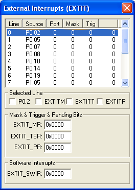
External Interrupts (EXTIT) Dialog

The External Interrupts Dialog displays the status of all simulated MCU external interrupts. The line, source, port, mask and interrupt state for each interrupt is displayed. You may select and configure each interrupt using the following control groups:
Selected Line
- XTIMn (Wake Up Mask - Line n) is set to allow an interrupt or a wake up event for the selected line.
- XTITn (Trigger Polarity - Line n) is set an interrupt pending status on the rising edge of the input wake up line. If reset, the interrupt pending status is set on the falling edge.
- XTIPn (Interrupt Pending - Line n) is set when an interrupt is triggered for the selected line.
Mask & Trigger & Pending Bits
- XTI_MRH (Wake Up Mask - Bits 8-15) are set to allow an interrupt or a wake up event.
- XTI_MRL (Wake Up Mask - Bits 0-7) are set to allow an interrupt or a wake up event.
- XTI_TRH (Trigger Polarity - Bits 8-15) are set an interrupt pending status on the rising edge of input wake up. If reset, the interrupt pending status is set on the falling edge.
- XTI_TRL (Trigger Polarity - Bits 0-7) are set an interrupt pending status on the rising edge of input wake up. If reset, the interrupt pending status is set on the falling edge.
- XTI_PRH (Interrupt Pending - Bits 8-15) are set when an interrupt is triggered.
- XTI_PRL (Interrupt Pending - Bits 0-7) are set when an interrupt is triggered.
Wake Up Control & Software Interrupts
- XTI_CTRL (Wake Up Control Register) contains the STOP, ID1S and WKUP-INT bit settings.
- XTI_SR (Software Interrupt Register) contains the 8 software interrupt pending bits. Bits are set when software interrupts are pending.
- WKUP-INT (Wake Up Interrupt) when set, the 16 wake up lines become wake up sources for exiting the STOP mode. If reset, the 16 wake up lines can be used to generate interrupt requests on IRQ5 of the EIC.
- ID1S (Global Interrupt Mask) is set to enable XTI interrupts. If reset, XTI interrupts are disabled.
- STOP (Stop Bit) setting, resetting then setting this bit again in sequence (1,0,1) puts the MCU in the STOP mode. The WKUP-INT must also be set, there must be no pending bits set and at least 1 mask bit must be set.
ProductsDevelopment Tools |
Hardware & Collateral |
Downloads |
Support |
Contact |
