|
||
| Products Download Events Support Videos | ||
Product Information
Device Database®
Downloads
Compliance Testing
Distributors
Peripheral Simulation
For Silicon Laboratories, Inc. C8051T602 — PCA Timer with modules
Simulation support for this peripheral or feature is comprised of:
- Dialog boxes which display and allow you to change peripheral configuration.
These simulation capabilities are described below.
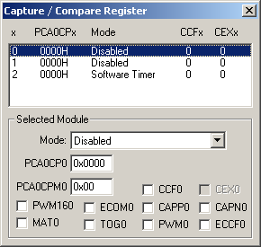
Capture / Compare Register Dialog

The Capture/Compare Register Dialog controls simulation all of the six operation modes of the PCA0 capture/compare module.
Selected Module
- Mode is the mode for the selected capture compare register.
- PCA0CPn (PCA Capture Module Register) hold the data used for capture and compare functions.
- PCA0CPMn (PCA0 Capture/Compare Mode Registers)
- CCFn (Module n Capture/Compare Flag) is set when a match or capture occurs fro module n.
- PWM16n (16-bit Pulse Width Modulation Enable) is set to select 16-bit PWM. If reset, 8-bit PWM is selected.
- ECOMn (Comparator Function Enable) is set to enable the comparator function.
- CAPPn (Capture Positive Function Enable) is set to enable the positive edge capture function.
- CAPNn (Capture Positive Function Enable) is set to enable the negative edge capture function.
- MATn (Match Function Enable) is set to enable the match function.
- TOGn (Toggle Function Enable) is set to toggle the CEXn pin when a match occurs.
- PWMn (Pulse Width Modulation Mode Enable) is set to enable Pulse Width Modulation output on the CEXn pin.
- ECCFn (Capture/Compare Flag Interrupt Enable) is set to enable the compare/capture flag interrupt.
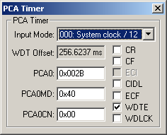
PCA Timer Dialog

The PCA Timer Dialog controls simulation all of the 16-bit PCA counter/timer.
PCA Timer
- Input Mode is the mode for the selected capture/compare register.
- WDT Offset (Watchdog Timer Offset) is the time, in milliseconds, before the WDT will expire.
- PCA0 (PCA Counter Timer Register) holds the counter or timer value used by the PCA.
- PCA0CN (PCA Control Register) contains the PCA Timer run control and overflow flag.
- CR (PCA Counter/Timer Run Control) is set to enable the PCA counter/timer.
- CF (PCA Counter/Timer Overflow Flag) is set to cause a PCA interrupt when an overflow occurs.
- ECI (External Clock Input) is set to use the external clock as the PCA clock source.
- PCA0MD (PCA Mode Register) contains the following control bits:
- CIDL (PCA Counter/Timer Idle Control) is set to suspend PCA operation when the system controller is in idle mode.
- ECF (PCA Counter/Timer Overflow Interrupt Enable) is set to enable a PCA interrupt when CF is set.
- WDTE (Watchdog Timer Enable) is set to enable PCA module 4 as a WDT.
- WDLCK (Watchdog Timer Lock) is set to lock the WDT.
ProductsDevelopment Tools |
Hardware & Collateral |
Downloads |
Support |
Contact |
