|
||
| Products Download Events Support Videos | ||
Product Information
Device Database®
Downloads
Compliance Testing
Distributors
Peripheral Simulation
For STMicroelectronics STR710FZ1 — Enhanced Interrupt Controller (EIC)
Simulation support for this peripheral or feature is comprised of:
- Dialog boxes which display and allow you to change peripheral configuration.
These simulation capabilities are described below.
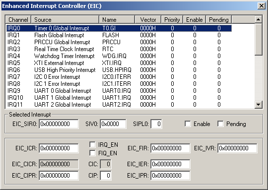
Enhanced Interrupt Controller Dialog

The Enhanced Interrupt Controller Dialog displays the status of all simulated MCU interrupts. The channel, source, name, vector, priority and interrupt state for each interrupt is displayed. You may select and configure each interrupt using the following control groups:
Selected Interrupt
- EIC_SIRn (Source Interrupt Register - Channel n) contains the following bit settings:
- SIVn (Source Interrupt Vector - Channel n) can contain the ISR address offset or lower part of the first ISR instruction.
- SIPLn (Source Interrupt Priority Level - Channel n) allows you to manually set a priority level of 0 - 15 for this interrupt.
- Enable is checked when this interrupt is enabled. You may manually enable the interrupt by setting this bit.
- Pending is checked when this interrupt occurred but has not been serviced. You may manually trigger the interrupt by setting this bit.
- EIC_ICR (Interrupt Control Register) contain the following bit settings:
- IRQ_EN (IRQ Output Enable) is set to enable IRQ output requests.
- FIQ_EN (FIQ Output Enable) is set to enable FIQ output requests.
- EIC_CICR (Current Interrupt Channel Register) displays 32-bit register containing the channel number of the interrupt being serviced.
- CIC (Current Interrupt Channel) displays the channel number of the interrupt being serviced.
- EIC_CIPR (Current Interrupt Priority Register) displays 32-bit register containing the priority value of the interrupt being serviced.
- CIP (Current Interrupt Priority) displays the priority value (0-15) of the interrupt being serviced.
- EIC_FIR (Fast Interrupt Register) contains the Fast Interrupt Enable (bits 0 and 1) and Fast Interrupt Pending (bits 2 and 3) bits. To enable a fast interrupt, both bits 0 and 1 must be set. Bits 2 and 3 indicate the source of the interrupt.
- EIC_IVR (Interrupt Vector Register) contains the interrupt vector of a pending interrupt. Reading this register tells the EIC that the pending interrupt is being serviced.
- EIC_IER (Interrupt Enable Register) is used to enable interrupts for one or more of the 32 interrupt input channels. Setting a bit enables the interrupt for the corresponding channel.
- EIC_IPR (Interrupt Pending Register) is used to display interrupts pending for one or more of the 32 interrupt input channels.
ProductsDevelopment Tools |
Hardware & Collateral |
Downloads |
Support |
Contact |
