|
||
| Products Download Events Support Videos | ||
Product Information
Device Database®
Downloads
Compliance Testing
Distributors
Peripheral Simulation
For Infineon XC164CM-8F — PEC
Simulation support for this peripheral or feature is comprised of:
- Dialog boxes which display and allow you to change peripheral configuration.
These simulation capabilities are described below.
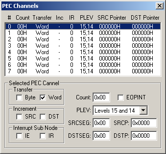
PEC Channels Dialog

The PEC (Peripheral Event Controller) Channels dialog shows the status of all PEC transfers. The configuration of each PEC is displayed and may be changed using the appropriate control.
Selected PEC Channel
- Transfer specifies whether Bytes or Words are transferred for each PEC interrupt.
- Increment specifies whether the source pointer (SRC) and/or the destination pointer (DST) increment after each transfer.
- Interrupt Sub Node specifies whether node sharing interrupt requests or enable flags are supported for the selected source.
- Count specifies the number of transfers to make.
- EOPINT (End of PEC Interrupt) is set when End of PEC interrupts occur on a different PEC level.
- PLEV (PEC Interrupt Level) displays the interrupt level assignment to the selected PEC channel.
- SRCSEG (Source Pointer Segment) contains the source segment for the selected channel.
- SRCP specifies the source address (in the first 64K).
- DSTSEG (Destination Pointer Segment) contains the destination segment for the selected channel.
- DSTP specifies the destination address (in the first 64K).
ProductsDevelopment Tools |
Hardware & Collateral |
Downloads |
Support |
Contact |
