|
||
| Products Download Events Support Videos | ||
Product Information
Device Database®
Downloads
Compliance Testing
Distributors
Peripheral Simulation
For Analog Devices ADuC7026 — Flash/EE Memory
Simulation support for this peripheral or feature is comprised of:
- Dialog boxes which display and allow you to change peripheral configuration.
These simulation capabilities are described below.
Flash/EE Memory Dialog

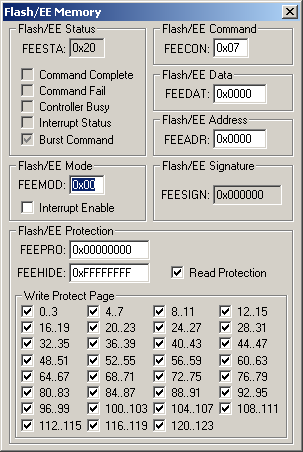
The Flash/EE Memory dialog displays and configures the on-chip Flash/EE Memory provided with the ADuC7000 series devices. The controls in this dialog are separated into several logical groups.
Flash/EE Status Group
- FEESTA (Flash/EE Status Register) contains the following Flash/EE status bits:
- Command Complete is set when a command successfully completes.
- Command Fail is set when a command does not successfully complete.
- Controller Busy is set when the Flash/EE controller is busy.
- Interrupt Status is set when a command completes and the Flash/EE interrupt enable bit is set.
- Burst Command is set when a burst command is sent to the Flash/EE controller.
Flash/EE Command Group
- FEECON (Flash/EE Command Register) contains the current Flash/EE command.
Flash/EE Data Group
- FEEDAT (Flash/EE Data Register) contains the current Flash/EE data value.
Flash/EE Address Group
- FEEADR (Flash/EE Address Register) contains the current Flash/EE address where the current data will be loaded or written to.
Flash/EE Mode Group
- FEEMOD (Flash/EE Mode Register) contains only the Flash/EE interrupt enable bit.
- Interrupt Enable is set when the Flash/EE interrupt is enabled.
Flash/EE Signature Group
- FEESIGN (Flash/EE Signature Register) displays the 24-bit Flash/EE signature value.
Flash/EE Protection Group
- FEEPRO (Flash/EE Protection Register) contains the composite Flash/EE protection setting. It is protected by a 32-bit access key value which must be written to FEEDAT and FEECON.
- FEEHIDE (Flash/EE Hide Register) contains the read protection and write protection settings below. These settings can be written to FEEPRO only after the proper access key is provided.
- Read Protection is set to prevent the Flash/EE from being read through JTAG or parallel programming modes.
Write Protection Page Group
- n..m sets write protection for pages in groups of 4. n is the low page number, m is the high page number.
ProductsDevelopment Tools |
Hardware & Collateral |
Downloads |
Support |
Contact |
