|
||
| Products Download Events Support Videos | ||
Product Information
Device Database®
Downloads
Compliance Testing
Distributors
Peripheral Simulation
For Analog Devices ADuC7021 — SPI
Simulation support for this peripheral or feature is comprised of:
- Dialog boxes which display and allow you to change peripheral configuration.
These simulation capabilities are described below.
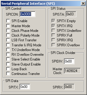
Serial Peripheral Interface Dialog

The Serial Peripheral Interface (SPI) dialog configures the simulation of this interface. Simulation is controlled by modifying the checkboxes in the following groups:
SPI Control Group
- SPICON (SPI Control Register) controls the basic operating mode of the SPI controller and contains the following control bits:
- SPI Enable is set to enable the SPI controller.
- Master Mode is set to configure this controller for master mode.
- Clock Phase Mode is set to pulse the serial clock at the start of each bit transfer.
- Clock Polarity Mode sets the clock idle level to a high state.
- LSB First Transfer is set to transmit the least significant bit (LSB) of each data byte first.
- Transfer & IRQ Mode is set to start transfers by writing to the SPITX register. An interrupt will occur when the transmitter is empty.
- TX Underflow Mode is set to transmit the previous data.
- RX Overflow Overwrite is set to allow the data in the receive register to be overwritten by the next data byte received.
- Slave Select Enable (Slave Select Input Enable) is set by the master to allow slave input.
- Slave Output Enable is set to allow slave output.
- Loop Back is set to internally connect the transmit and receive (MISO and MOSI) pins for testing purposes.
- Continuous Transfer is set to allow the master to transfer data until no data is available in the transmit register (SPITX).
SPI Status Group
- SPISTA (SPI Status Register) displays the following status information:
- SPITX Empty is set when the transmit register is empty.
- SPITX IRQ is set either SPITX Empty or SPITX Underflow is set.
- SPITX Underflow is set when the transmit register underflows.
- SPIRX Full is set when there is valid data in the receive register (SPIRX).
- SPIRX IRQ is set either SPIRX Full or SPIRX Overflow is set.
- SPIRX Overflow is set when the receive register overflows.
SPI Clock Divider Group
- SPIDIV (SPI Divider Register) contains the clock divisor divided by 2, minus 1 used to calculate the Master Clock frequency.
- Master Clock contains the calculated SPI clock frequency.
SPI SPI Data Group
- SPITX (SPI Transmit Register) contains the next data byte to be transmitted.
- SPIRX (SPI Receive Register) displays the last data byte received.
ProductsDevelopment Tools |
Hardware & Collateral |
Downloads |
Support |
Contact |
