|
||
| Products Download Events Support Videos | ||
Product Information
Device Database®
Downloads
Compliance Testing
Distributors
Peripheral Simulation
For Atmel AT91M42800A — System Timer: Period Interval Timer, Watchdog Timer, Real Time Timer
Simulation support for this peripheral or feature is comprised of:
- Dialog boxes which display and allow you to change peripheral configuration.
These simulation capabilities are described below.
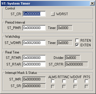
System Timer Dialog

The System Timer Dialog shows the current state of the on-chip Period Interval, Watchdog and Real-time Timers. You can change settings for these timers using the controls in this dialog.
Control Group
- ST_CR (Control Register) holds the Watchdog Timer Restart (WDRST) value.
- WDRST (Watchdog Timer Restart) when set, reloads the start-up value into the Watchdog Timer./li
Period Interval Group
- ST_PIMR (Period Interval Mode Register) holds the Period Interval Value that loads into the Period Interval Timer.
Watchdog Group
- ST_WDMR (Watchdog Mode Register) holds the Watchdog Counter Value (WDV) and the Reset Enable (RSTEN) and External Signal Assertion Enable (EXTEN) status.
- RSTEN (Reset Enable) generates an internal reset when a watchdog overflow occurs.
- EXTEN (External Signal Assertion Enable) holds NWDOVF signal low for 8 clock cycles when a watchdog overflow occurs.
Real Time Group
- ST_RTMR (Real-time Mode Register) contains the number of Slow Clock (SLCK) periods required to increment the Real-time Timer.
- ST_RTAR (Real-time Alarm Register) contains the value to compare against the Real-time counter.
- Divider
- ST_CRTR (Current Real-time Register) contains the current value of the Real-time Timer.
Interrupt Mask & Status Group
- ST_IMR (Interrupt Mask Register) controls the system timer interrupts described below.
- ST_SR (Status Register) displays the system timer interrupt status described below.
- ALMS (Alarm Status) The upper checkbox enables the Alarm Status interrupt. The lower checkbox is set when the Real-time counter value equals the Real-time Alarm (ST_RTAR) value.
- RTTINC (Real-time Timer Increment) The upper checkbox enables the Real-time Timer Increment interrupt. The lower checkbox is set each time the Real-time counter is incremented.
- WDOVF (Watchdog Overflow) The upper checkbox enables the Watchdog Overflow interrupt. The lower checkbox is set when the Watchdog Overflow occurs.
- PITS (Period Interval Timer Status) The upper checkbox enables the Period Interval Timer interrupt. The lower checkbox is set when the Period Interval Timer reaches zero.
ProductsDevelopment Tools |
Hardware & Collateral |
Downloads |
Support |
Contact |
