|
||
| Products Download Events Support Videos | ||
Product Information
Device Database®
Downloads
Compliance Testing
Distributors
Peripheral Simulation
For Atmel AT91M55800A — Advanced Power Management Controller
Simulation support for this peripheral or feature is comprised of:
- Dialog boxes which display and allow you to change peripheral configuration.
- VTREGs (Virtual Target Registers) which support I/O with the peripheral.
These simulation capabilities are described below.
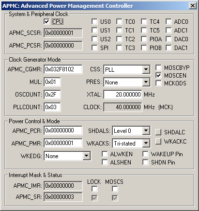
Advanced Power Management Controller Dialog

The Advanced Power Management Controller Dialog configures the power saving mode of the ARM controller by enabling and disabling the system and peripheral clocks.
System & Peripheral Clock Group
- The CPU box, if checked, stops the system clock, and forces the processor into Idle mode.
- PMC_SCSR (System Clock Status Register) displays the status of the CPU clock.
- PMC_PCSR (Peripheral Clock Status Register) displays the current status of the peripheral clock.
- US0 if set, enables the USART 0 clock.
- US1 if set, enables the USART 1 clock.
- US2 if set, enables the USART 2 clock.
- SPI if set, enables the Serial Peripheral Interface clock.
- TC0 if set, enables the Timer/Counter 0 clock.
- TC1 if set, enables the Timer/Counter 1 clock.
- TC2 if set, enables the Timer/Counter 2 clock.
- TC3 if set, enables the Timer/Counter 3 clock.
- TC4 if set, enables the Timer/Counter 4 clock.
- TC5 if set, enables the Timer/Counter 5 clock.
- PIOA if set, enables the parallel I/O A clock.
- PIOB if set, enables the parallel I/O B clock.
Clock Generator Mode Group
- APMC_CGMR (Clock Generator Mode Register) displays the composite value of the following clock generator components:
- MUL (Phase Lock Loop Factor) is the Phase Locked Loop multiplication ratio from 1 to 63. A value of 0 deactivates the Phase Locked Loop.
- OSCOUNT (Main Oscillator Counter) is the number of 4096 Hz clock cycles allowed for the main oscillator to stabilize after it is enabled.
- PLLCOUNT (PLL Lock Counter) is the number of 32,768 Hz clock cycles before the PLL is locked.
- CSS (Clock Source Selection) selects the clock source.
- PRES (Prescaler Selection) selects the scaling factor for the selected clock.
- XTAL is the oscillator frequency.
- CLOCK is the master clock frequency.
- MOSCBYP (Main Oscillator Bypass) if set, requires an external clock signal on XIN.
- MOSCEN (Main Oscillator Enable) enables the main oscillator.
- MCKODS (Master Clock Output Disable) If set, the master clock output MCKO pin is tri-stated. If not set, MCKO is driven from the master clock (MCO).
Power Control & Mode Group
- APMC_PCR (Power Control Register) contains the following shut-down and wake-up controls:
- WKACKC (Wake-up or Alarm Acknowledge Command) configures the shut-down pin based on the WKACKS value.
- SHDALC (Shut-down or Alarm Command) configures the shut-down pin based on the SHDALS value.
- APMC_PMR (Power Mode Register) defines the way the shut-down, wake-up and alarm features are used.
- SHDALS (Shut-down or Alarm Output Selection) defines the state of the SHDN pin.
- WKACKS (Wake-up or Alarm Acknowledge Output Selection) defines the state of the WAKEUP pin.
- WKEDG (Wake-up Input Edge Selection) defines the edge level needed to generate a wake-up.
- ALWKEN (Alarm Wake-up Enable) if set, allows the real-time clock to generate a wake-up.
- ALSHEN (Alarm Shut-down Enable) if set, allows the real-time clock to generate a shut-down.
- WAKEUP Pin displays or sets the state of this output pin.
- SHDN Pin displays or sets the state of this output pin.
Interrupt Mask & Status Group
- APMC_IMR (Interrupt Mask Register) displays the main oscillator and PLL Lock interrupt mask settings.
- APMC_SR (Status Register) displays the main oscillator (MOSCS) and PLL Lock Status (LOCK).
- LOCK (PLL Lock Interrupt Disable) If set, disables the PLL Lock interrupt.
- MOSCS (Main Oscillator Interrupt Disable) if set, disables the Main Oscillator interrupt.
SHDN VTREG
Data Type: unsigned char
THE SHDN VTREG contains the state of the SHDN pin on the simulated MCU.
WAKEUP VTREG
Data Type: unsigned char
THE WAKEUP VTREG contains the state of the WAKEUP pin on the simulated MCU.
ProductsDevelopment Tools |
Hardware & Collateral |
Downloads |
Support |
Contact |
