|
||
| Products Download Events Support Videos | ||
Product Information
Device Database®
Downloads
Compliance Testing
Distributors
Peripheral Simulation
For Infineon C509-L — System Configuration
Simulation support for this peripheral or feature is comprised of:
- Dialog boxes which display and allow you to change peripheral configuration.
These simulation capabilities are described below.
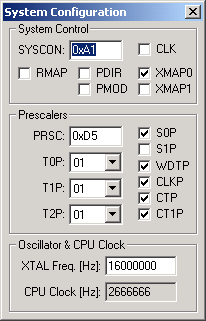
System Configuration Dialog

The System Configuration Dialog controls the various system-wide functions of the microcontroller. These functions are listed below:
System Control
- SYSCON (System Control Register) contains the register mapping, external RAM and other configuration settings.
- CLK (Clockout Enable) is set output the system clock on the P1.6/CLKOUT pin.
- RMAP (Special Function Register Map) is set to enable access to the mapped SFR area. It is reset to enable access to the standard SFR area.
- PDIR (Port Direction Enable) is set to read or write the direction registers on the next instruction cycle. The hardware automatically resets this bit on the second instruction cycle after the bit is set.
- PMOD (Port 5 Mode Selection) is set to select the Port 5 bidirectional port structure.
- XMAP0 (Global XRAM/CAN Controller Access Enable/Disable Control) is set to disable access to XRAM and CAN controller. Resetting this bit enables access to these devices.
- XMAP1 (XRAM/CAN Controller Visible Access Control) is set to allow address and data information during XRAM or CAN accesses to be externally visible using ports 0 and 2.
Prescalers
- PRSC (Prescaler Control Register) contains the frequency divisor ratio for Timers 0, 1 and 2.
- T0P (Timer 0 Divisor Ratio) selects the divisor ratio used to calculate Timer 0 event timing.
- T1P (Timer 1 Divisor Ratio) selects the divisor ratio used to calculate Timer 1 event timing.
- T2P (Timer 2 Divisor Ratio) selects the divisor ratio used to calculate Timer 2 event timing.
- S0P (Serial Interface 0 Prescaler) is set to divide the serial interface 0 baud rate by 2.
- S1P (Serial Interface 1 Prescaler) is set to divide the serial interface 1 baud rate by 2.
- WDTP (Watchdog Input Clock Prescaler Select) is set to reduce the watchdog timer clock frequency by one-half.
- CLKP (Clock Output (CLKOUT) Prescaler) is set to generate a system clock that is 1/12 the oscillator frequency. It is reset to generate a system clock that is 1/6 the oscillator frequency.
- CTP (Compare Timer Prescaler) is set to further divide the computed Compare Timer Input clock by 2.
- CT1P (Compare Timer 0 Prescaler) is set to further divide the computed Compare Timer 1 Input clock by 2.
Oscillator & CPU Clock
- XTAL Freq. [Hz] is the oscillator frequency at XTAL.
- CPU Clock [Hz] is the CPU clock rate based on the XTAL frequency.
ProductsDevelopment Tools |
Hardware & Collateral |
Downloads |
Support |
Contact |
