 |
USB Component
Version 6.17.0
MDK Middleware for USB Device and Host Communication
|
|
USB Component
Version 6.17.0
MDK Middleware for USB Device and Host Communication
|
Using the custom USB class, you can implement any USB device that is not covered by the other classes available in the MDK Middleware. An example is available for various development boards that is implementing a custom class to work with the Windows USB (WinUSB), a generic driver for USB devices for Microsoft Windows. The example demonstrates a WinUSB device that contains Bulk IN and Bulk OUT endpoints. All data that the device receives on the Bulk OUT endpoint is echoed back on the Bulk IN endpoint.
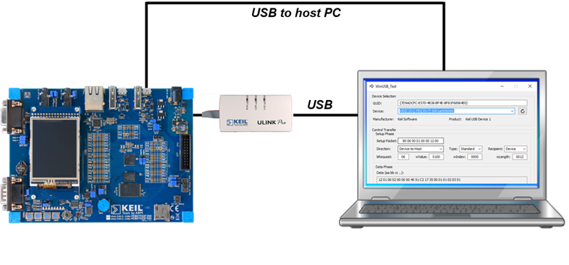
The following picture shows an exemplary connection of the development board and the Windows USB host computer. Using the USB connection and WinUSB_Test.exe (available in "install_dir\ARM\PACK\Keil\MDK-Middleware\x.y.z\Utilities\WinUSB_Test\Release\" folder, where "install_dir" refers to the installation directory of Arm Keil MDK, usually "C:\Keil_v5" and x >= 7, y >= 5, z >= 0), you can initiate Bulk/Interrupt/Control Transfers. For more information, refer to WinUSB Test.
The Abstract.txt file contained in the Documentation group of the Project window gives you more information on the general setup.
Open the example project in MDK. The µVision Project window should display a similar project structure:

If you are using RTOS other than CMSIS-RTOS2 RTX5 for your project please make sure to satisfy USB Device Resource Requirements.
You may now build and download the example project to the evaluation board using the µVision commands:
After these steps, the project should start executing on your evaluation kit. In case of errors, refer to the Evaluation Board User's Guide for configuration information.
The setup of the evaluation board hardware is described in the Abstract.txt file.
The example can be tested on a Windows PC using the WinUSB_Test.exe utility provided with MDK Middleware. The program runs stand-alone without installation. Simply run "install_dir\ARM\PACK\Keil\MDK-Middleware\x.y.z\Utilities\WinUSB_Test\Release\WinUSB_Test.exe" application (where x >= 7, y >= 5, z >= 0):
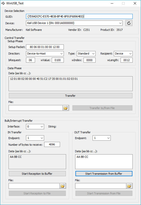
Device Selection
| Configuration Option | Selection |
|---|---|
| GIUD | The GUID that is used in Windows to access the device. For this example, the GIUD is fixed. To create your own GIUD, refer to the Abstract.txt file. |
| Device | Select the device that you have attached to the PC (VID should be C251). |
Control Transfer
| Configuration Option | Selection |
|---|---|
| Setup Packet | Normally, leave open. Will be filled automatically from the next options. |
| Direction | Specify the communication direction. If you want to read for example the device descriptor from the device, use Device-to-Host. |
| Type | Type of the control request (standard/class/vendor). |
| Recipient | Recipient of the control transfer message (device/interface/endpoint/other). |
| bRequest | Specify the setup packet request being made. |
| wValue | Specify the wValue of the request. |
| wIndex | Specify the wIndex of the request. |
| wLength | Specify the wLength of the request. |
Data Phase
| Configuration Option | Selection |
|---|---|
| Data (aa bb cc ..) | Shows the transmitted data |
| Transfer button | Start the data transfer |
| File | Select a file for transfer or for saving transferred data |
| Transfer to/from File button | Start the data transfer to/from file |
Bulk/Interrupt Transfer
| Configuration Option | Selection |
|---|---|
| Interface | Select USB interface number |
| IN Transfer Endpoint | Select IN endpoint to be used for bulk/interrupt transfer |
| Number of bytes to receive | Specify the number of bytes to be received |
| Data (aa bb cc ..) | Shows the received data |
| Start Reception button | Start listening on the specified endpoint |
| File | Select a file for saving received data |
| Start Reception to File button | Start listening on the specified endpoint and save data to file |
| OUT Transfer Endpoint | Select OUT endpoint to be used for bulk/interrupt transfer |
| Data (aa bb cc ..) | Enter the data to be transmitted |
| Start Transmission button | Start sending data on the specified endpoint |
| File | Select a file for data to be transmitted |
| Start Transmission from File button | Start sending data from the specified file on the OUT endpoint |
Control Transfer
To setup the control endpoint and to read out the device descriptor of the device, enter the following:
After pressing the Transfer button, you see the response in the Data window:
Bulk Transfer
To loop data from the device to the PC and back, enter the following:
You now see the same data in the left-hand Data window:
About Host PC driver for Microsoft Windows
The example folder contains two files relevant for driver installation on the Microsoft Windows:
The driver files are provided as an example, the driver setup information file should be adapted and digitally signed driver catalog file should be created from adapted driver setup information file.
Driver setup information file should be adapted in the following way:

